Roadway electric generator

a technology of electric generator and road, which is applied in the direction of electric generator control, machines/engines, mechanical equipment, etc., can solve the problems of no application to roadway or traffic use for the generation of energy sources, and none of the prior art patents located in the prior art have the capacity for electrical energy generation

Inactive Publication Date: 2003-02-20
SLATKIN JEFFREY H
View PDF13 Cites 51 Cited by
  • Summary
  • Abstract
  • Description
  • Claims
  • Application Information

AI Technical Summary

Problems solved by technology

None of these located prior art patents have the capacity for the generation of electrical energy

Method used


Image

  • Roadway electric generator
  • Roadway electric generator
  • Roadway electric generator

Examples


Embodiment Construction

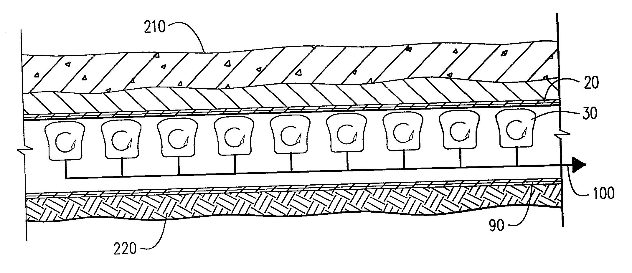
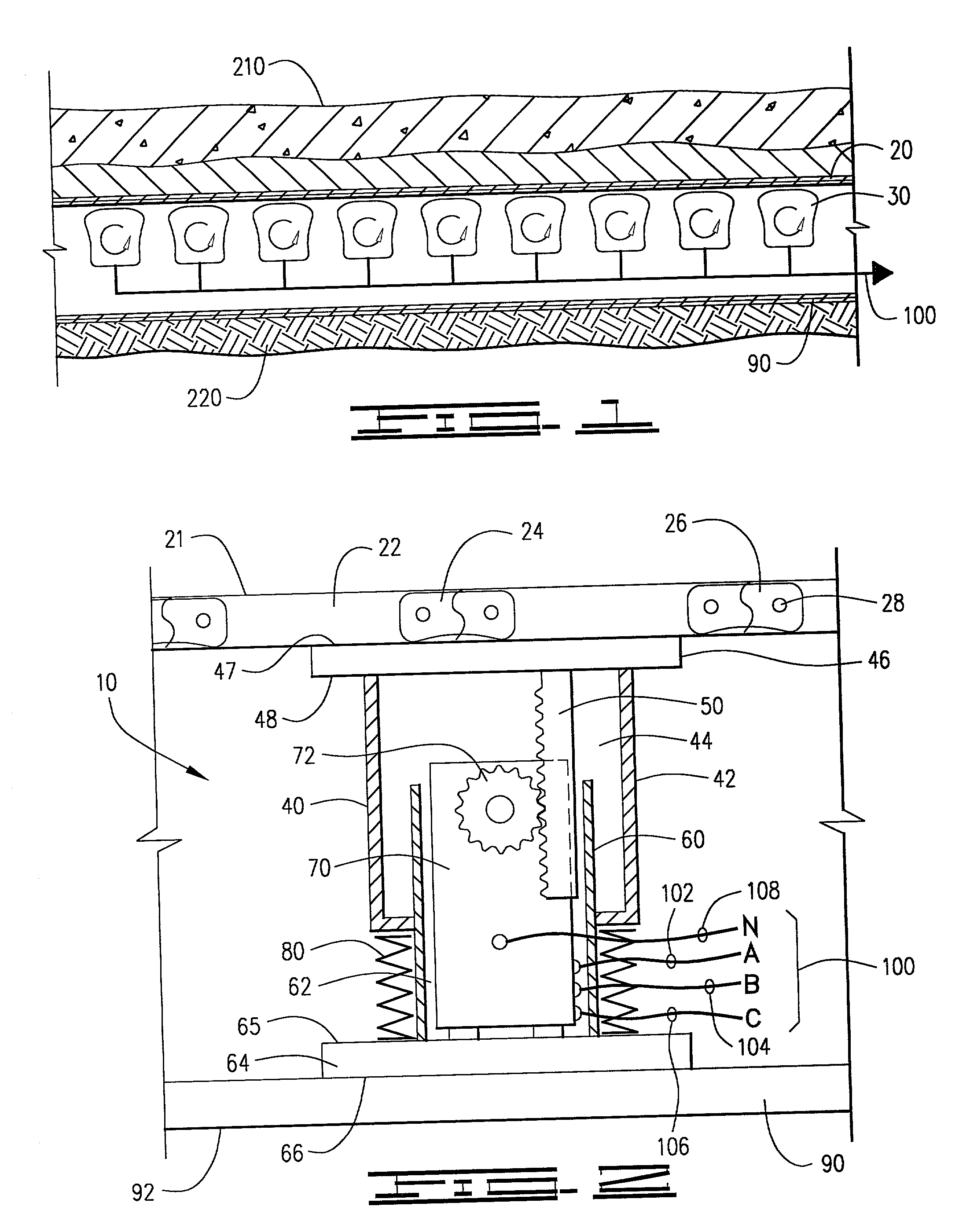
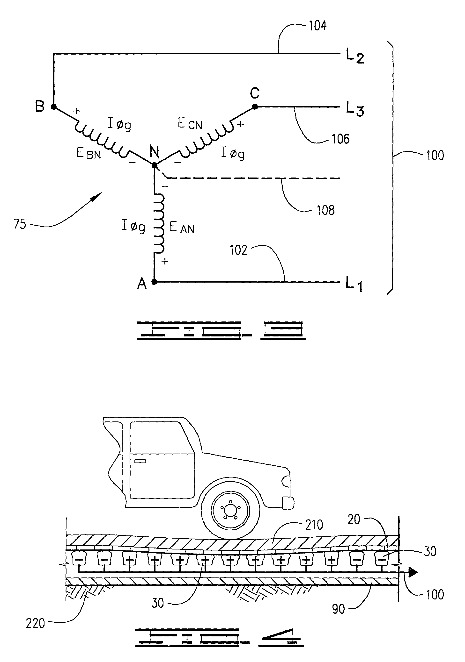
[0018] The invention is a device and method of producing electrical energy by using the potential energy of automobile traffic in a roadway 200, the device 10, as shown in FIGS. 1-4 of the drawings, comprising a deformable upper plate 20, a plurality of electro-mechanical generating pumps 30 producing a usable electrical current, a rigid lower plate 90, and electrical conductor wires 100, the device embedded within the roadway 200 wherein passing vehicular traffic compresses the deformable upper plate 20, compressing the electro-mechanical generating pumps 30 between the deformable upper plate 20 and the rigid lower plate 90, such compression producing such usable electrical current through the electrical conductor wires 100.

[0019] In furtherance of this invention, the deformable upper plate 20, as shown in FIGS. 2 and 4 of the drawings, has an upper surface 21, and is a series of individual rigid tread plates 22 linked together by a linking means 24, which, in a preferred embodimen...


PUM


Abstract

The invention is an electrical generating device and method utilizing the potential energy of moving traffic on highways to generate three phase electrical current, the device comprising a large plurality of compressible electrical generator pumps underneath upper and lower plates located between the road bed and the travel surface of the highway activated by the compression weight of a moving vehicle over the travel surface of the roadway.

Description

[0001] NoneI. BACKGROUND OF THE INVENTION[0002] 1. Field of Invention[0003] The invention is an electrical generating device and method utilizing the potential energy of moving traffic on highways to generate three phase electrical current, the device comprising a large plurality of compressible electrical generator pumps underneath upper and lower plates located between the road bed and the travel surface of the highway activated by the compression weight of a moving vehicle over the travel surface of the roadway.[0004] 2. Description of Prior Art[0005] The following United States patents were discovered and are disclosed within this application for utility patent. All relate to electrical devices located in a roadway, most of them pertaining to traffic control sensing devices. None of these located prior art patents have the capacity for the generation of electrical energy.[0006] In U.S. Pat. No. 3,535,923 to Martorana, et al., a load sensing transducer located underneath a roadbe...

Claims


Application Information

Patent Timeline
IPC IPC(8): F03G7/08H02K7/18
CPCF03G7/08H02K7/1853
Inventor SLATKIN, JEFFREY H.
Owner SLATKIN JEFFREY H
Why Eureka
Try Eureka