
Photocell with fluorescent conversion layer

Inactive Publication Date: 2003-03-27
BIOMED SOLUTIONS
View PDF0 Cites 36 Cited by
  • Summary
  • Abstract
  • Description
  • Claims
  • Application Information

AI Technical Summary

Problems solved by technology

Commercially available prior art devices for converting light to electricity are relatively inefficient.
However, efficient crystalline-based devices, especially of large surface area, are difficult and expensive to produce due to the problems inherent in producing large crystals without significant efficiency-degrading defects."

Method used


Image

  • Photocell with fluorescent conversion layer
  • Photocell with fluorescent conversion layer
  • Photocell with fluorescent conversion layer

Examples


Embodiment Construction

[0008] The process of this invention provides increased conversion of light to electricity. This efficiency, often referred to as "conversion efficiency," refers to the efficiency of the process of converting light energy to electrical energy within a photovoltaic device.

[0009] Photocells are characterized by the efficiency with which they can convert incident light energy to useful electrical energy. Devices utilizing crystalline or amorphous silicon dominate commercial applications, and some have achieved efficiencies of 23% or greater. However, efficient crystalline-based devices, especially of large surface area, are difficult and expensive to produce due to the problems inherent in producing large crystals without significant efficiency-degrading defects. More recent efforts have focused on the use of organic photovoltaic cells to achieve acceptable photovoltaic conversion efficiencies with economical production costs, but in general the materials used in these devices are not ...


PUM


Abstract

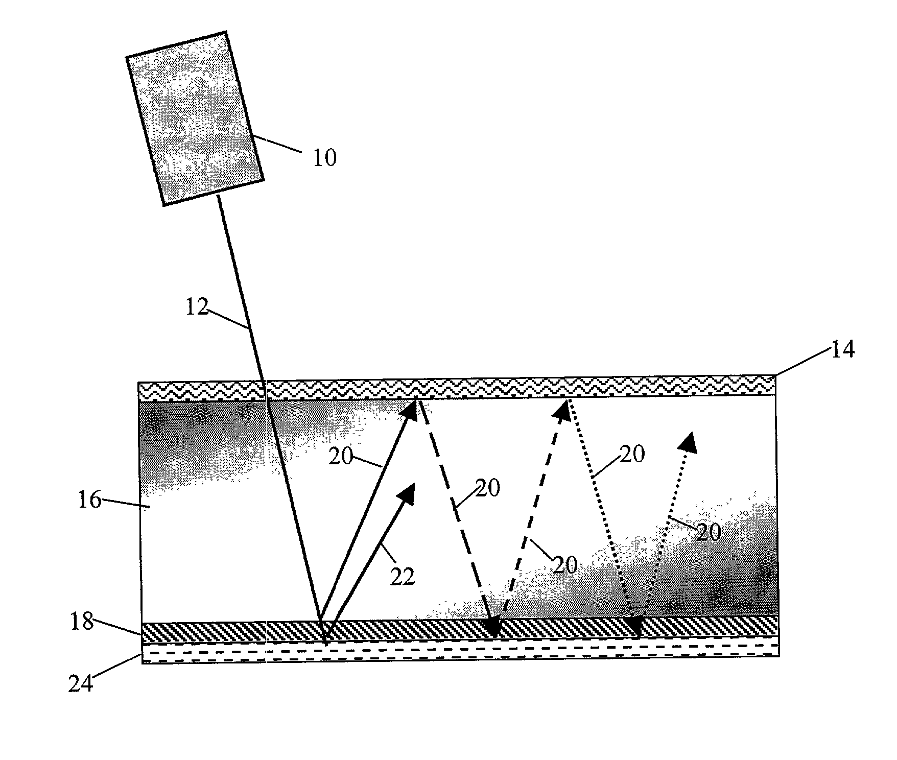
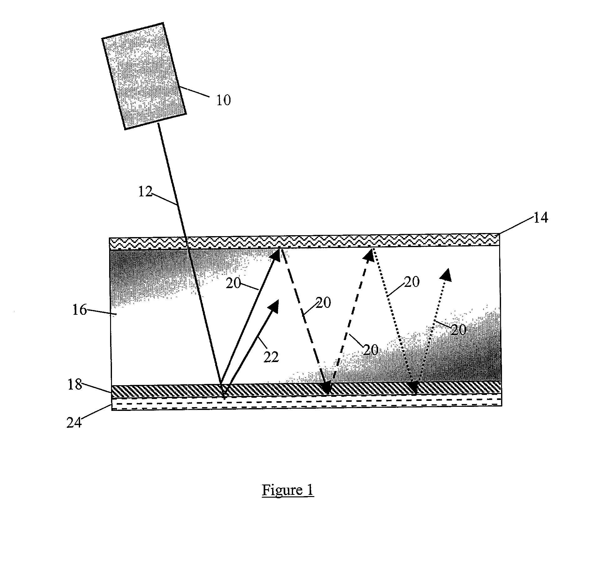
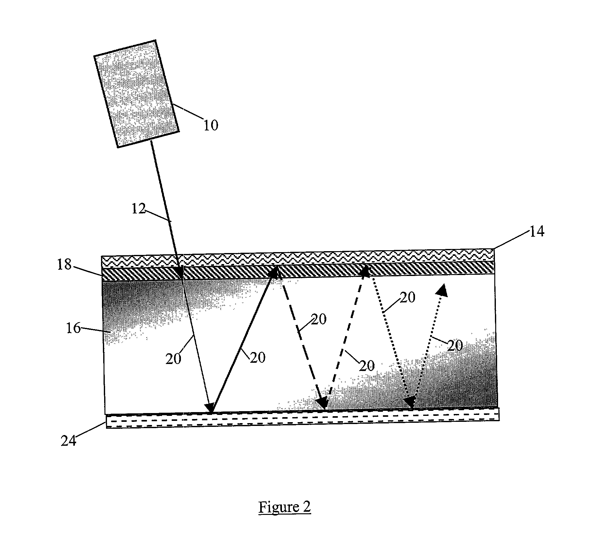
A photocell device having enhanced conversion efficiency. The device is adapted to convert light energy to electrical energy in a semiconductor layer, to convert a first, monochromatic light, to a second light of different wavelength, in a fluorescent layer, to transmit the first light through a hot mirror layer, to reflect light from the hot mirror layer, and to reflect light from a mirror layer disposed at a second surface of the device.

Description

FIELD OF THE INVENTION[0001] A process for converting light to electricity at an efficiency of at least about fifty percent.BACKGROUND OF THE INVENTION[0002] Commercially available prior art devices for converting light to electricity are relatively inefficient. These commercially available devices include photocells, which are characterized by the efficiency with which they can convert incident light energy to useful electrical energy. In general, such efficiency does not exceed about 23 percent. Thus, as is disclosed in U.S. Pat. No. 6,278,055, " . . . photosensitive optoelectronic devices have been constructed of a number of inorganic semiconductors. . . . Solar cells are characterized by the efficiency with which they can convert incident solar power to useful electric power. Devices utilizing crystalline or amorphous silicon dominate commercial applications and some have achieved efficiencies of 23% or greater. However, efficient crystalline-based devices, especially of large s...

Claims


Application Information

Patent Timeline
IPC IPC(8): H01L31/0232
CPCH01L31/02322Y02E10/52
Inventor MACDONALD, STUART G.
Owner BIOMED SOLUTIONS
Learn More