Vertebral spacer for spinal stabilization

a technology of vertebral spacers and spacers, which is applied in the direction of internal osteosynthesis, prosthesis, osteosynthesis devices, etc., can solve the problems of time-consuming and dangerous, difficult, or impossible, to place an intermedullary rod after a cage-type spacer, and many of the devices presently available, especially cage-type spacers, to achieve the effect of reducing the risk of fracture, time-consuming and dangerous, and avoiding fractur

Inactive Publication Date: 2003-05-01
SPINEOLOGY
View PDF0 Cites 106 Cited by
  • Summary
  • Abstract
  • Description
  • Claims
  • Application Information

AI Technical Summary

Problems solved by technology

Many of the devices presently available, particularly cage-type spacers, are difficult to place, or utilize at all, with a previously positioned intermedullary rod.
With many of these devices, it is also difficult, or impossible, to place an intermedullary rod after a cage-type spacer is inserted.
Simultaneously placing both devices can be awkward, time consuming and dangerous.
But, if the cage has already been placed into position, it is nearly impossible to place the intermedullary rod without first cutting a slot or otherwise damaging the cage by indenting the case to form a deep groove.

Method used


Image

  • Vertebral spacer for spinal stabilization
  • Vertebral spacer for spinal stabilization
  • Vertebral spacer for spinal stabilization

Examples


second embodiment

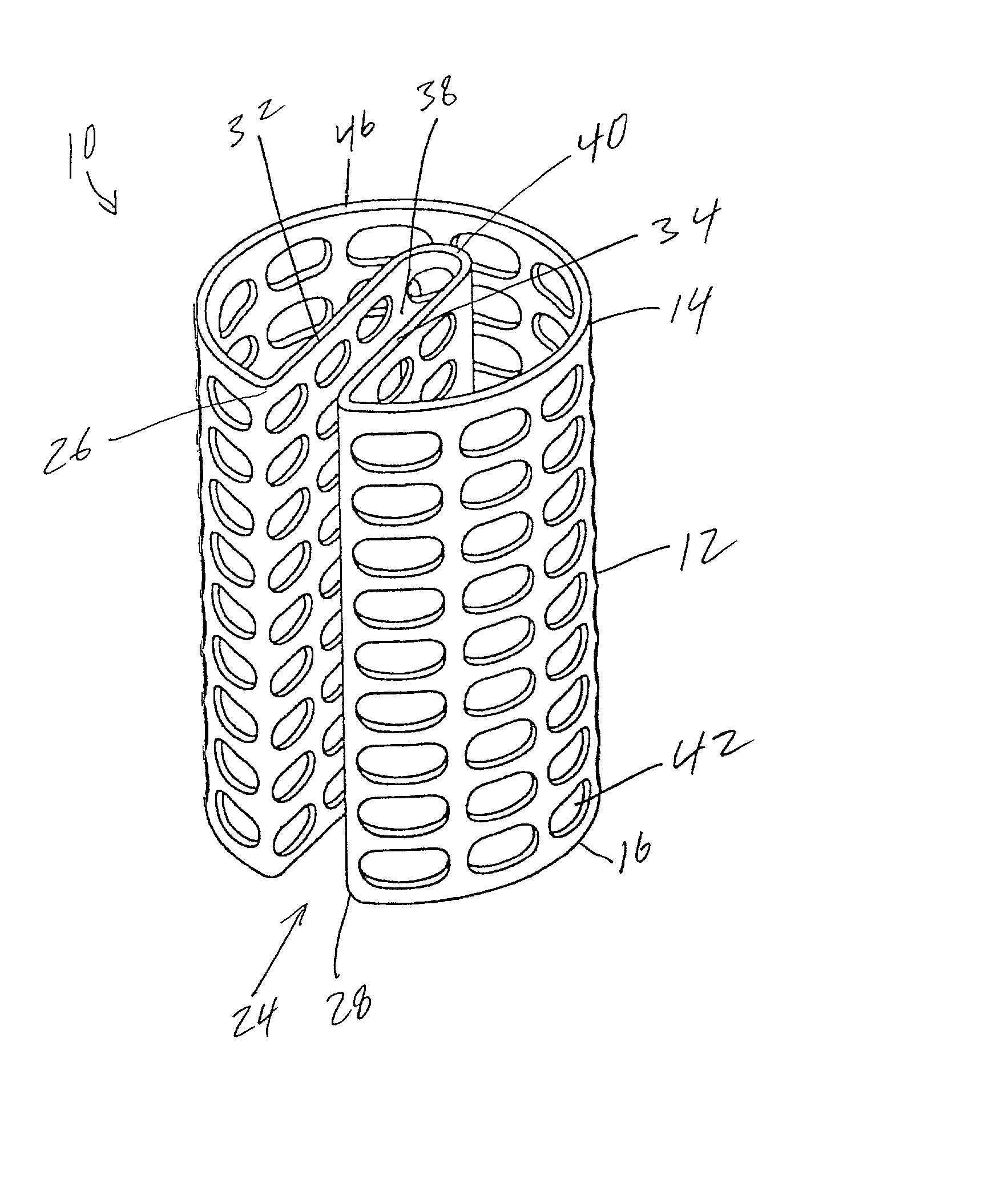
[0057] In a second embodiment shown in FIGS. 4 and 5 the device 10 includes a first guide wall 32 extends inwardly from the edge 26 and a second guide wall 34 extends inwardly from the edge 28 to form a slot 36 into which an intermedullary rod 50 (shown in FIG. 8) may be positioned. Walls 32 and 34 are preferably parallel. Walls 32 and 34 act to guide a rod or other member into the slot 36. The walls 32 and 34 may be spaced to engage a rod and ensure proper placement of the device 10 into a spinal cavity or space already containing a rod therewithin.

third embodiment

[0058] In a third embodiment shown in FIGS. 6-8, the discontinuity 24 is configured as a groove or invagination 38. The groove 38 is comprised of the inwardly extending guide walls 32 and 34 which extend inward from the edges 26 and 28. In the present embodiment however, the walls 32 and 34 are continuous being joined together at a junction 40 to form the U-shaped groove 38. Groove 38 is constructed and arranged to receive an intermedullary rod 50 (shown in FIG. 8) between the walls 32 and 34. The position of the junction 40 allows the device 10 to engage a rod 50 already in place between spinal bodies, such that the rod acts as a guide post to ensure proper positioning of the device within a spinal cavity.

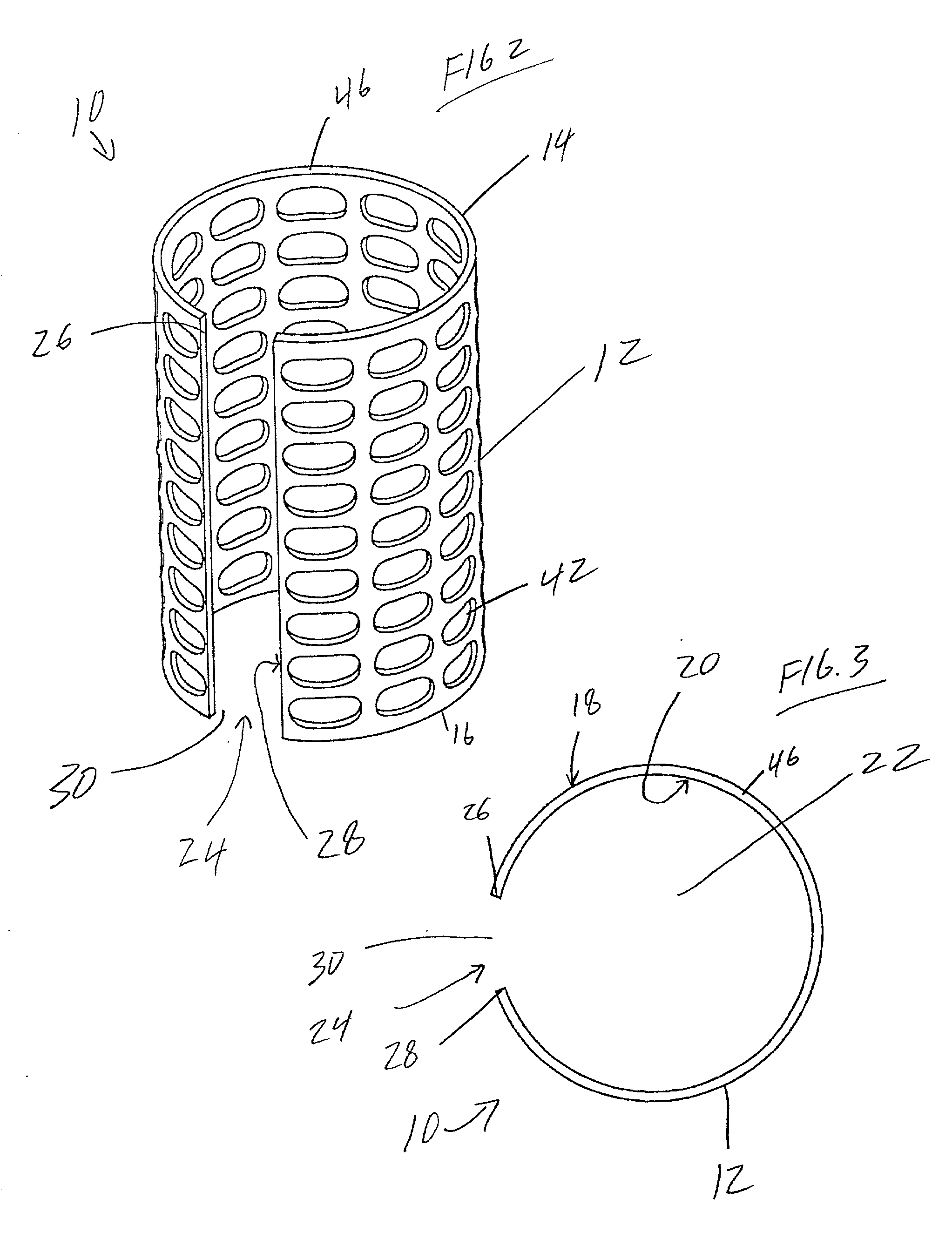
[0059] In the embodiments shown in FIGS. 2-7 the longitudinal discontinuity 24 will define a space of about 5 mm to about 10 mm between the first edge 26 and second edge 28.

[0060] In the various embodiments shown in FIGS. 1-8, the body 12 of device 10 may be constructed from any b...


PUM

PropertyMeasurementUnit
lengthaaaaaaaaaa
lengthaaaaaaaaaa
diameteraaaaaaaaaa

Abstract

A device for implantation into a mammalian spine which comprises: a body having a first end and a second end. The first end constructed and arranged to engage a lower surface of a spinal body when the body is implanted into an intervertebral space within the mammalian spine. The second end constructed and arranged to engage an upper surface of a spinal body when the body is implanted into an intervertebral space of the mammalian spine. The body defines an interior space. The body further includes a first edge and a second edge which define a longitudinal discontinuity extending from the first end of the body to the second end of the body, wherein the longitudinal discontinuity may be a space, slot or groove.

Description

[0001] Not Applicable[0002] Not Applicable[0003] 1. Field of the Invention[0004] Certain diseases and injuries damage the spinal tissues. This damage may lead to spinal instability. Instability of the spine may cause pain, and / or mal-alignment, and / or neurological impairment. Surgeons frequently treat these conditions with operations designed to correct these instabilities and mal-alignments. These operations generally involve implanting fixation devices to re-align and / or restabilize the spine.[0005] 2. Description of the Related Art[0006] In repairing a damaged portion or portions of a spine or spinal body, total or sub-total removal of the vertebra and / or discs may be necessary to decompress the spinal canal when disease and / or injury causes massive destruction of the spinal bones and the surrounding discs. Reconstruction of the resulting defect is necessary to regain spinal stability. Devices used to reconstruct such defects are commonly referred to as interbody spacers, spinal ...

Claims


Application Information

Patent Timeline
Patent Type & Authority Applications(United States)
IPC IPC(8): A61B17/70A61F2/00A61F2/28A61F2/30A61F2/44
CPCA61B17/70A61F2310/00365A61F2/30771A61F2/44A61F2/4465A61F2/447A61F2002/2817A61F2002/2821A61F2002/2835A61F2002/30092A61F2002/30133A61F2002/30143A61F2002/30149A61F2002/30151A61F2002/30153A61F2002/30154A61F2002/30156A61F2002/30225A61F2002/3023A61F2002/30237A61F2002/30331A61F2002/3055A61F2002/30678A61F2002/30747A61F2002/30777A61F2002/30779A61F2002/30784A61F2002/30787A61F2002/3082A61F2002/30836A61F2002/30841A61F2002/4475A61F2210/0014A61F2220/0033A61F2230/0015A61F2230/0017A61F2230/0019A61F2230/0021A61F2230/0023A61F2230/0069A61F2310/00017A61F2310/00023A61F2310/00179A61F2/30744A61F2002/30593A61F2002/30677
Inventor KUSLICH, STEPHEN D.
Owner SPINEOLOGY
Why Eureka
Try Eureka