Steering and handling device for moving roll cages

a technology for handling devices and rolling cages, which is applied in the direction of hand carts, transportation and packaging, children's carriages/perambulators, etc. it can solve the problems of inability to move the cage in time. , to achieve the effect of facilitating the engagement and disengagement of the channel, moving safely, and bringing the devi

Inactive Publication Date: 2003-05-15
SMITH MATTHEW JOSEPH +1
View PDF0 Cites 5 Cited by
  • Summary
  • Abstract
  • Description
  • Claims
  • Application Information

AI Technical Summary

Benefits of technology

The invention is a device that can safely and easily steer and handle existing roll cages without modifying them. The device has channel means that engage with the roll cage's base frame, allowing for smooth movement. The device also has a resilient connection between the body and the steering member to assist in engagement and disengagement of the channel means with the roll cage. The axle is mounted on the steering tiller, and the device can be locked in a straight-ahead position. The device also has wheels that do not foul the roll cage when steering it. The technical effects of this invention are improved efficiency and ease of use for steering and handling roll cages.

Problems solved by technology

The technical problem addressed in this patent is to provide a safe and stable steering and handling device for A-frame roll cages, which can be easily operated by shop assistants or warehousing personnel in a potentially crowded environment.

Method used


Image

  • Steering and handling device for moving roll cages
  • Steering and handling device for moving roll cages
  • Steering and handling device for moving roll cages

Examples


Embodiment Construction

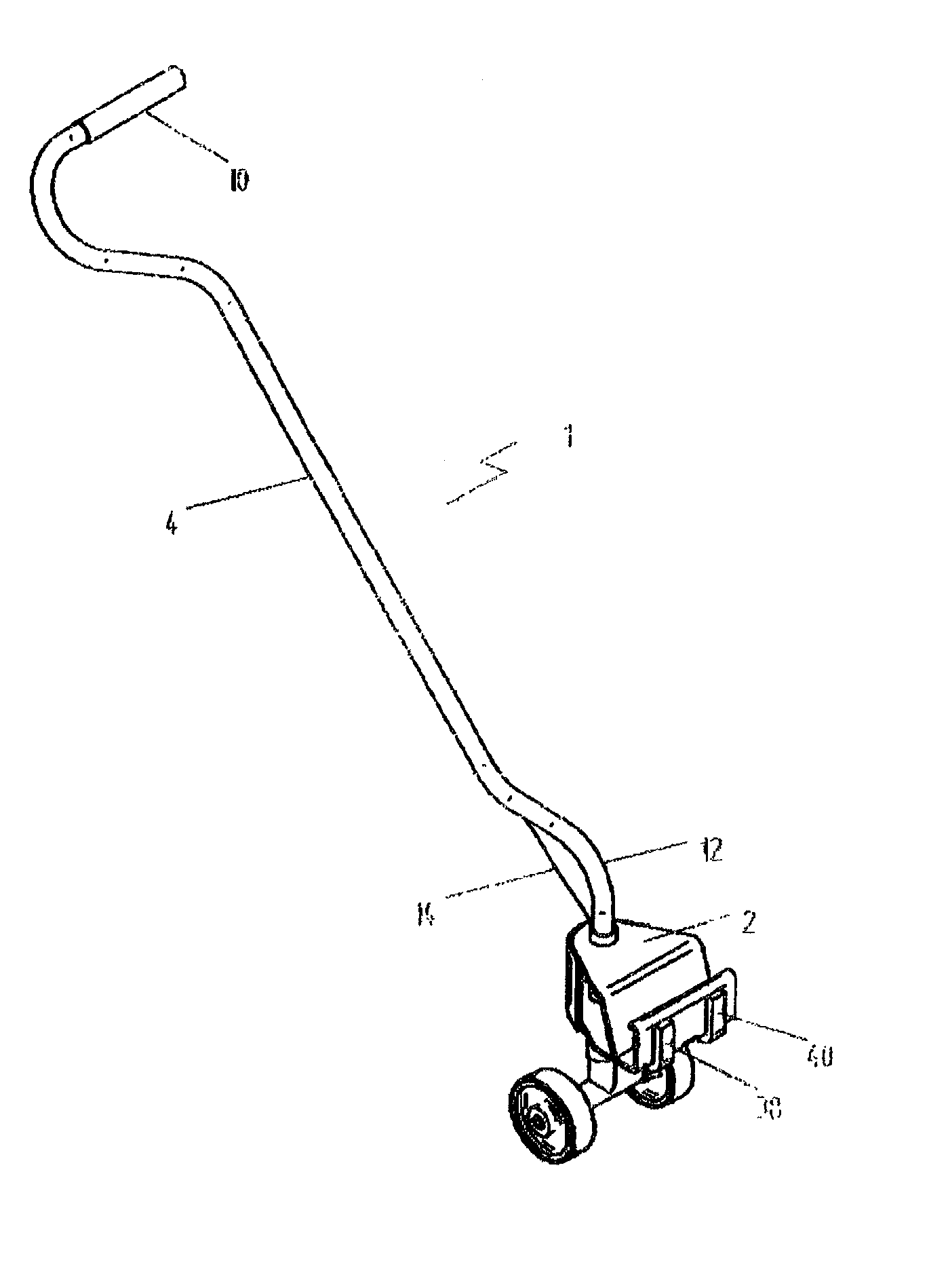
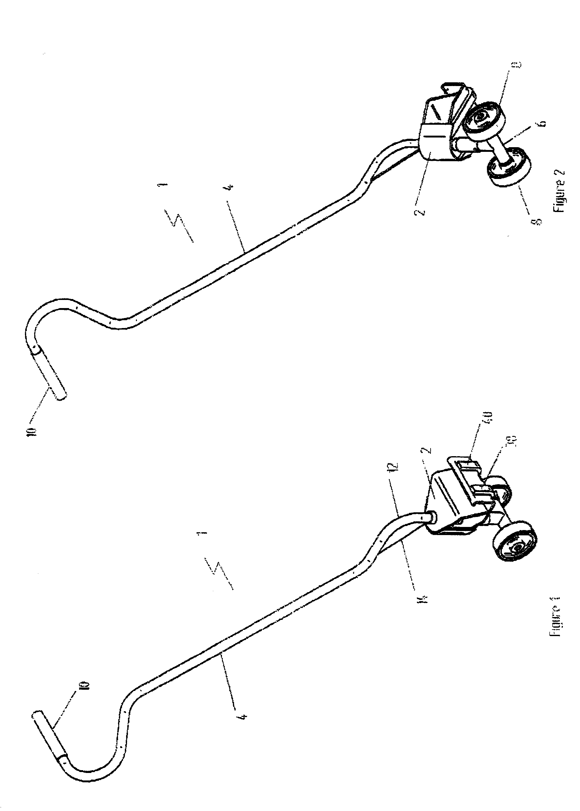
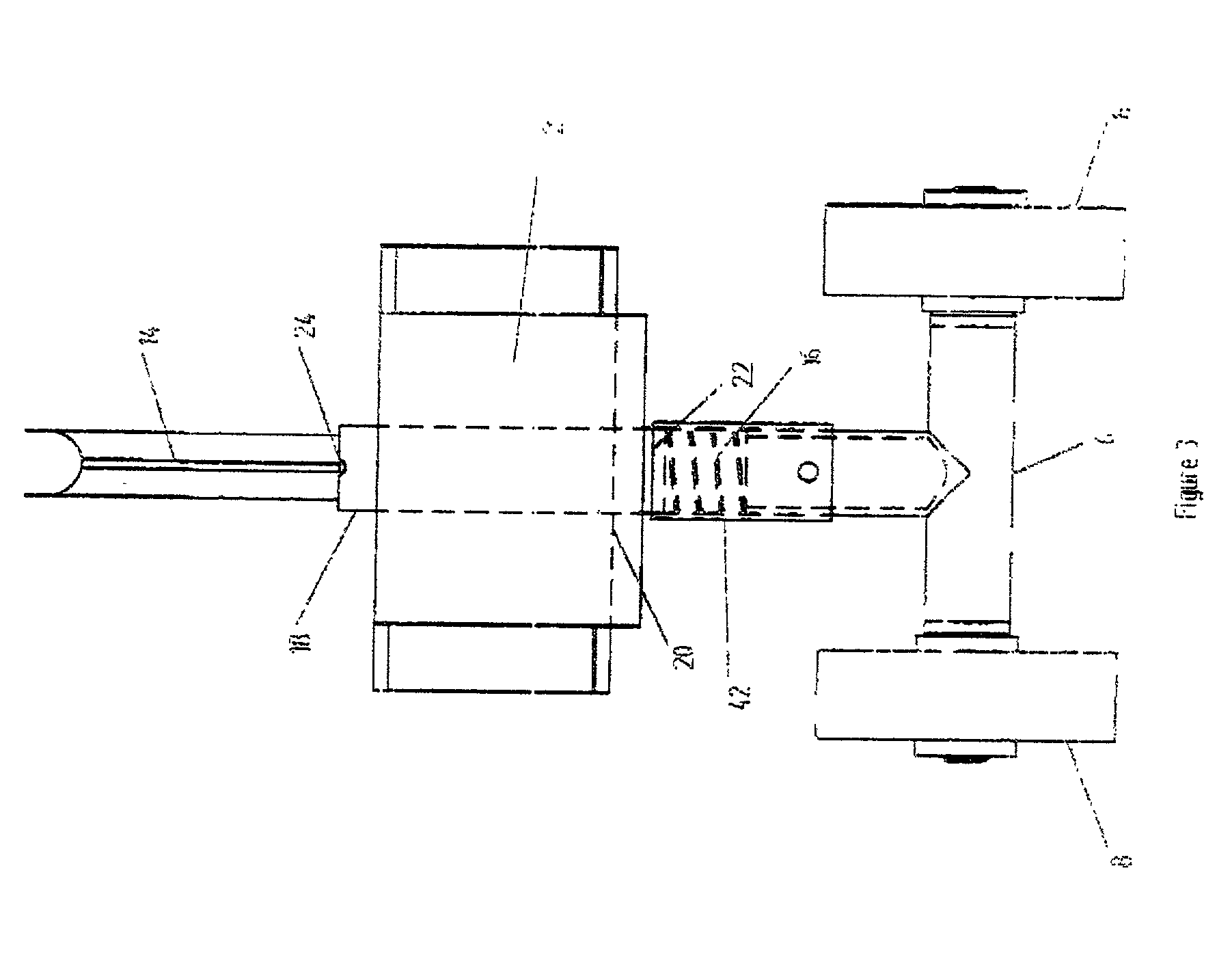
[0018] A steering and handling device (hereinafter refereed to as the "device") according to the present invention will be described with reference to FIGS. 1 to 4. The device 1 includes a body 2 and a steering tiller 4. The lower end of the steering tiller 4 passes through a pair of holes in the body 2 so that it is pivotally mounted. An axle 6 is fast to the lower end of the steering tiller 4 beneath the body 2 and a steering wheel 8 is rotatably mounted at each end of the axle 6. Pivotal movement of the steering tiller 4 therefore causes the steering wheels 8 to turn so that the device 1 can be steered about a steering axis. The upper end of the steering tiller 4 terminates in a handle portion 10 and the lower end of the steering tiller 4 is joined to the upper end by means of a swan-necked portion 12 that is reinforced by a web 14. In use the lower end of the steering tiller 4 is vertical so that the steering axis is vertical, and the upper end extends forwardly and upwardly fro...


PUM


Abstract

A steering and handling device (1) for moving a roll cage (100) which has a generally U-shaped base frame (102) with castor wheels (106) at its forward end and fixed wheels at its rearward end (110). The device (1) includes a body (2) defining a steering axis and having channel means (36) extending in cantilever rearwardly of the steering axis. The channel means (36) is for releasably engaging the base frame (102) of the roll cage (100) between the front castor wheels (106). A steering tiller (4) is pivotally mounted on the body (2) and extends forwardly and upwardly from the body (2) and terminates in a handle portion (10). An axle (6) is fast to the steering tiller (4) beneath the body (2) on which wheels (8) are mounted.

Description


Claims


Application Information

Patent Timeline
Owner SMITH MATTHEW JOSEPH
Why Eureka
Try Eureka