
Vehicle passenger seat

a passenger seat and passenger technology, applied in the field of passenger seats, can solve the problems of no means, seated passengers will inevitably experience lower back discomfort, and the movement is not achieved without compromis

Inactive Publication Date: 2003-06-19
BE AEROSPACE INCORPORATED
View PDF13 Cites 72 Cited by
  • Summary
  • Abstract
  • Description
  • Claims
  • Application Information

AI Technical Summary

Benefits of technology

[0009] It is another object of the invention to provide a vehicle passenger seat that can be moved between an upright position and a reclined position.
[0011] It is another object of the invention to provide a vehicle passenger seat that includes armrests having an ergonomically improved manner of being stowed, and which eliminate the mass of the sections required for conventional, fold-up armrests.

Problems solved by technology

Although the seat backs of prior art seats typically move between 3 and 5 inches to arrive at a reclined position, such movement is not achieved without compromise.
Because the seat pan does not move in concert with the seat back, a seated passenger will inevitably experience lower back discomfort due to pelvic rotation and slouching after the seat back has been moved.
Such prior art seats offer no means for preventing such discomfort, and actually cause the slouching passenger to potentially irritate other passengers by occupying additional space.
Furthermore, sudden aft movement of the seat back can result in impact to the aft-seated passenger's knees, or to a computer sitting on an open tray table or on the passenger's knees.
While certain prior art passenger seats exist that include a mechanism for supporting the cushioned seat pan that also causes the pan to move in concert with the seat back, such mechanisms possess specific flaws.
Unless a foot rest has been installed on the seat, this upward motion will cause discomfort to the passenger's legs.
Because such seats have seat backs that move aft and seat pans that move forward and upward, the seats not only compromise circulation in the passenger's legs, but also actually occupy even more space than those seats whose cushioned seat pans do not move.
While moving the armrests into the space between adjacent seats does provide a convenient stowage solution, the solution is far from ideal.

Method used


Image

  • Vehicle passenger seat
  • Vehicle passenger seat
  • Vehicle passenger seat

Examples


Embodiment Construction

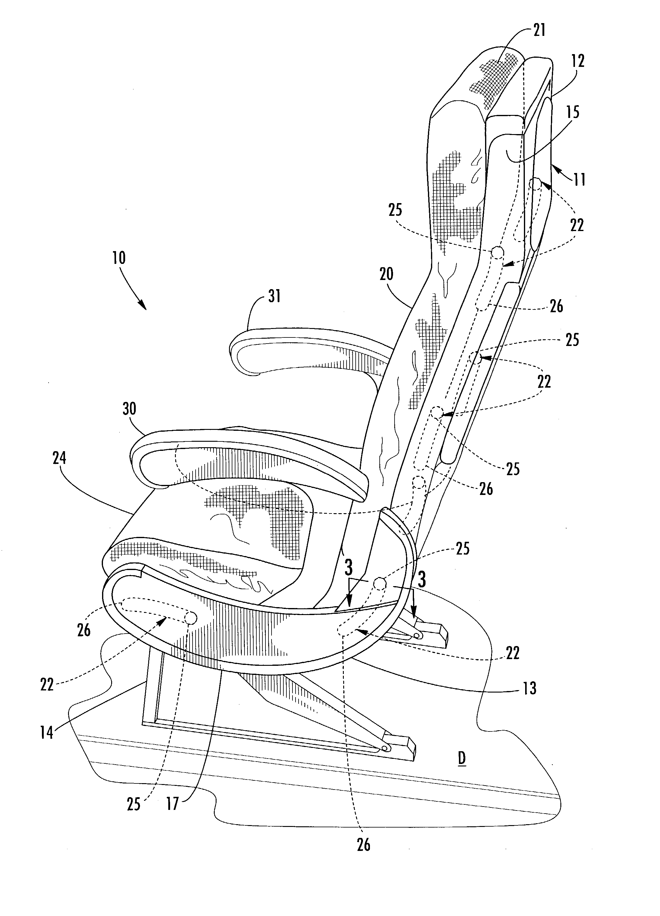
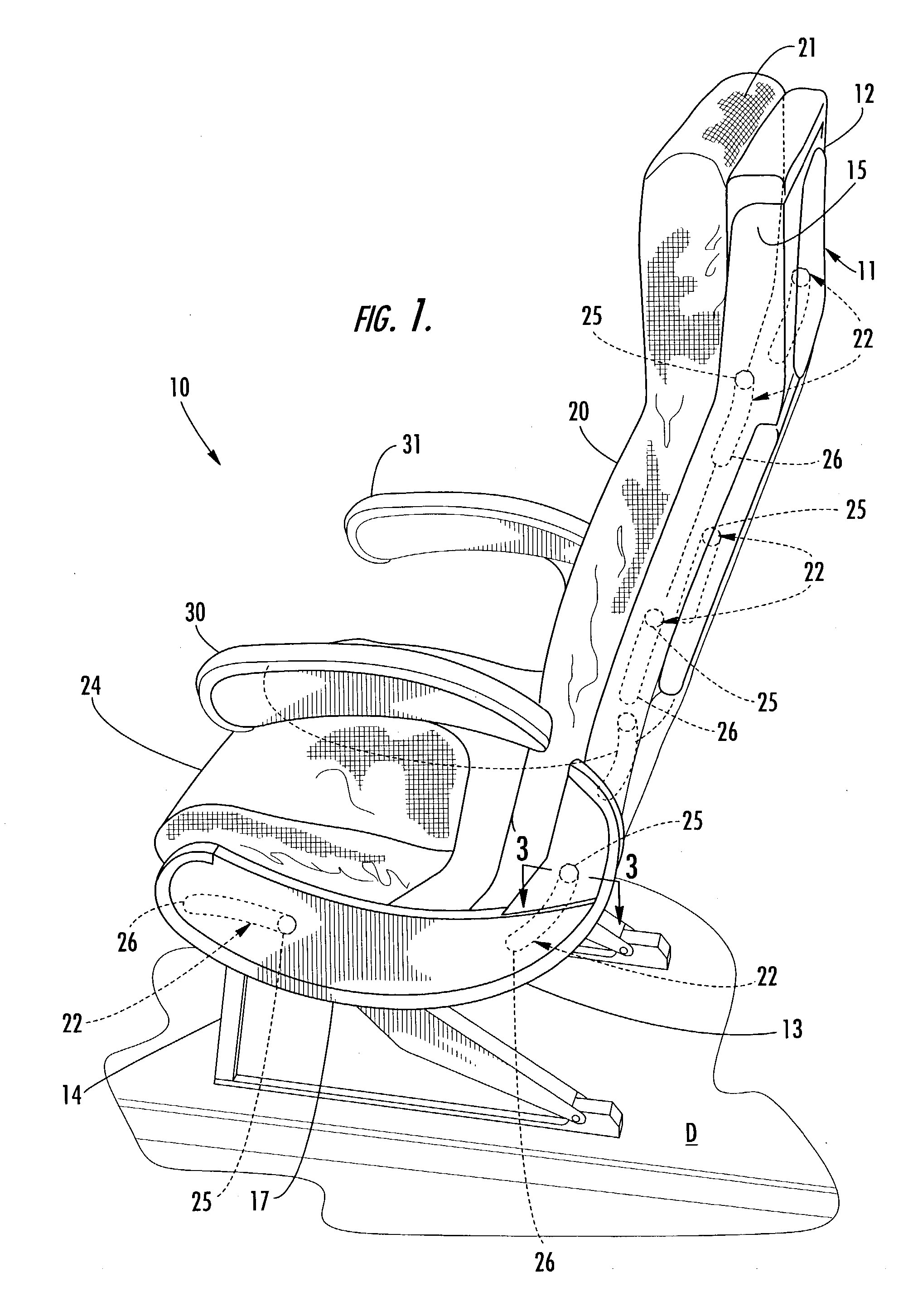
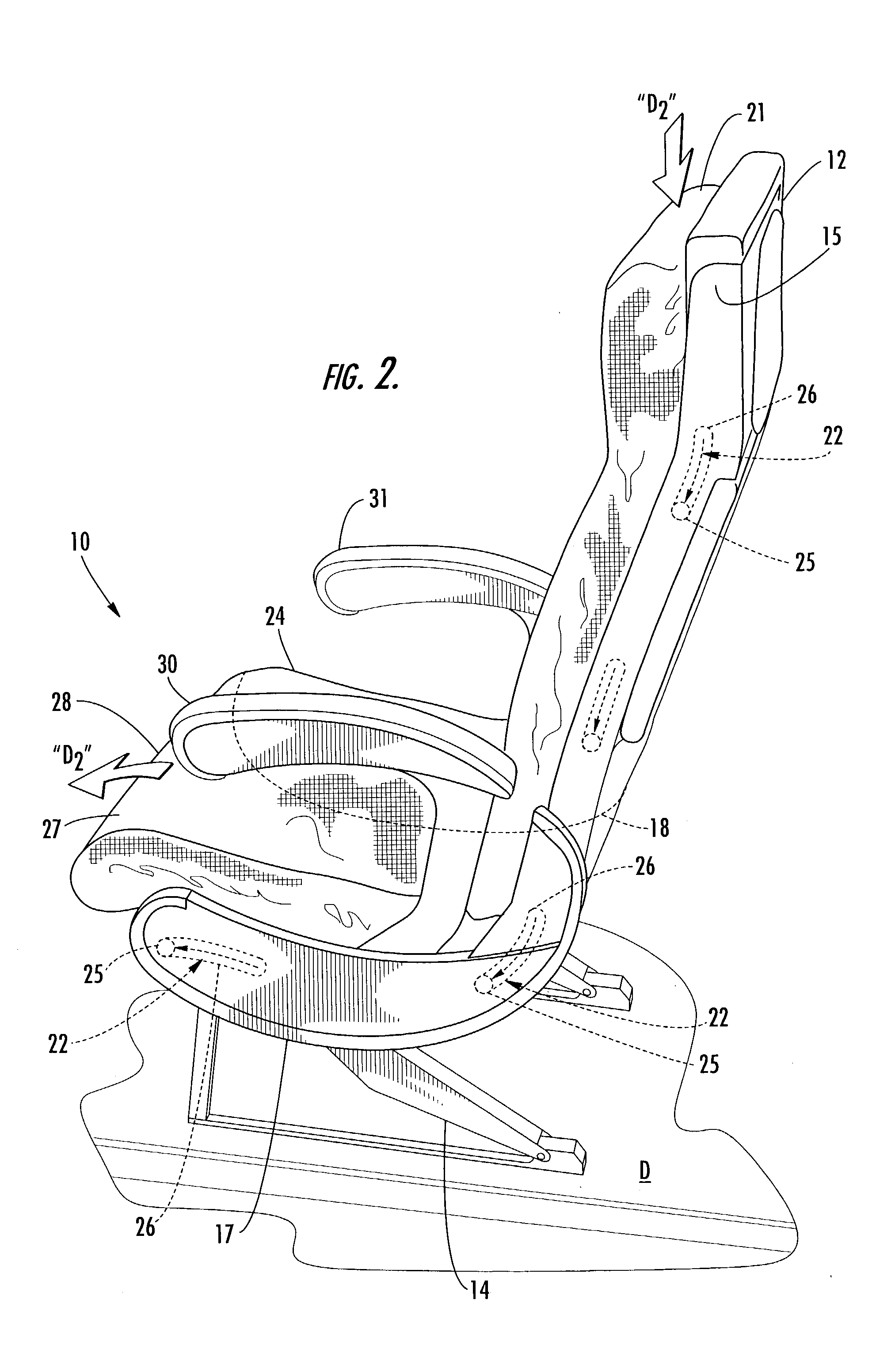
[0047] Referring now to FIG. 1, a passenger seat according to one preferred embodiment of the invention is illustrated and shown generally at reference numeral 10. The passenger seat 10 is shown in a fully upright position, and includes a stationary seat frame 11. The seat frame 11 is formed from a seat back frame member 12 and a seat bottom frame member 13. The seat bottom frame member 13 is affixed to a seat base 14, which is in turn mounted on the deck "D" of an aircraft. The seat back frame member 12 and seat bottom frame member 13 are positioned at a fixed angle relative to one another and to the seat base 14, which ensures that the seat frame 11 remains in a stationary position regardless of the extent to which any of other components of the seat 10 may move.

[0048] The seat back frame member 12 and seat bottom frame member 13 include pairs of spaced-apart lateral supports 15, 16 and 17, 18, respectively. Supports 16 and 18 are shown in FIG. 4. As is shown in FIG. 1, a cushione...


PUM


Abstract

A passenger seat including a seat base for being mounted on a support surface. A seat frame is carried by the seat base, and includes a seat bottom frame member and a seat back frame member is positioned in a fixed angular relation to each other and the seat base. A seat bottom pan is positioned on the seat bottom frame member. A seat back pan is positioned on the seat back frame member. Guide means cooperate with the bottom pan and bottom frame members and the back pan and back frame members, respectively, for unison translational movement of the back pan and the bottom pan between an upright position when the bottom pan is in the aft position and a recline position when the bottom pan is in the forward position.

Description

TECHNICAL FIELD AND BACKGROUND OF THE INVENTION[0001] This invention relates to a vehicle passenger seat intended for passenger conveyances including, but not limited to, buses, airplanes and trains. Although the passenger seat may be utilized in any type of vehicle, the passenger seat is preferably intended to be utilized for carrying economy class passengers in an aircraft. Unlike conventional passenger seats, the passenger seat of the present invention is capable of being quickly moved between upright and reclined positions without interfering with aft-seated passengers or compromising the safety and comfort of the seat.[0002] A conventional passenger seat typically includes a cushioned seat back and seat pan connected to a seat frame. The seat frame is affixed to the deck of an aircraft or other vehicle using conventional means. The seat pan is connected to the seat frame in a manner that maintains the seat pan in a stationary position, and the seat back is pivotally attached to...

Claims


Application Information

Patent Timeline
IPC IPC(8): B60N2/02B60N2/22B60N2/75B60N3/00B64D11/06
CPCB60N2/0284B60N2/2209B60N2/2236B60N2/4606B64D11/0646B60N3/004B64D11/06B64D11/0638B60N2/462B60N2/757B60N2/753B60N2/76B64D11/064B64D11/0644
Inventor BRENNAN, EDWARD J.
Owner BE AEROSPACE INCORPORATED
Learn More