
Fuel injection valve

a fuel injection valve and fuel technology, applied in the direction of fuel injection apparatus, machine/engine, feed system, etc., can solve the problems of improvable metering time and metered quantity of fuel, long closing time, and close the fuel injector

Inactive Publication Date: 2003-08-21
ROBERT BOSCH GMBH
View PDF7 Cites 11 Cited by
  • Summary
  • Abstract
  • Description
  • Claims
  • Application Information

AI Technical Summary

Benefits of technology

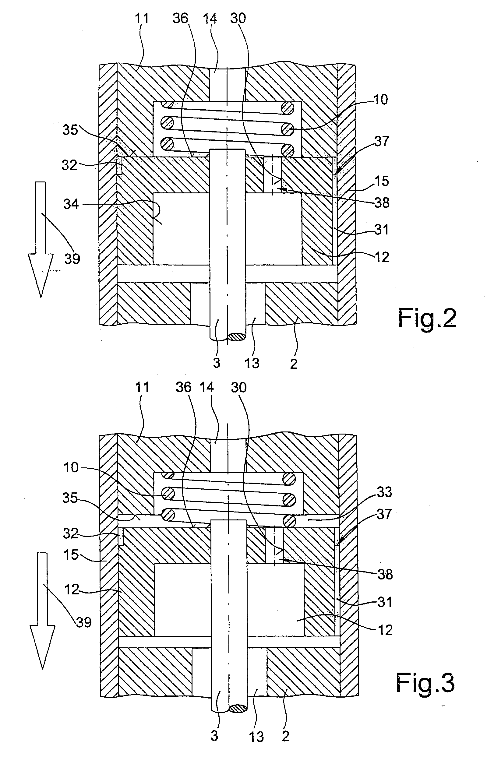
[0004] The fuel injector according to the present invention having the characterizing features of the main claim has the advantage over the related art that when a fuel channel with position-dependent cross-section is incorporated into the armature, the fuel builds up dynamic pressure in the armature, which operates in the direction of closure during the closing movement and accelerates the release of the armature from the internal pole. During the opening movement the dynamic pressure is considerably less, since the position-dependent cross-section of the fuel channel is largely open. The opening time therefore remains largely unimpaired by the measure according to the present invention. The quicker release of the armature from the internal pole as the magnetic field decays results in shorter closing times for the fuel injector, and thus in shorter and more precise fuel metering times and quantities. The fact that the activation power of the solenoid does not need to be increased to achieve shorter closing times is also advantageous.[0005] The measures listed in the subclaims make advantageous refinements of and improvements on the fuel injector described in the main claim possible.[0006] A second fuel channel whose cross-section is independent of the position of the armature is provided advantageously in the armature. This channel takes over the supplying of the fuel when the fuel injector is in the open position.[0007] Especially advantageous is the problem-free and economical production of an armature with appropriate bores and equalizing channels.

Problems solved by technology

A disadvantage of the fuel injector known from German Patent Application 195 03 821 A1 is in particular the relatively long closing times. Delays in closing the fuel injector are caused by the adhesive forces operating between the armature and the internal pole and by the non-instantaneous decay of the magnetic field when the exciting current is turned off.
This results in improvable metering times and metered quantities for the fuel.

Method used


Image

  • Fuel injection valve
  • Fuel injection valve
  • Fuel injection valve

Examples


Embodiment Construction

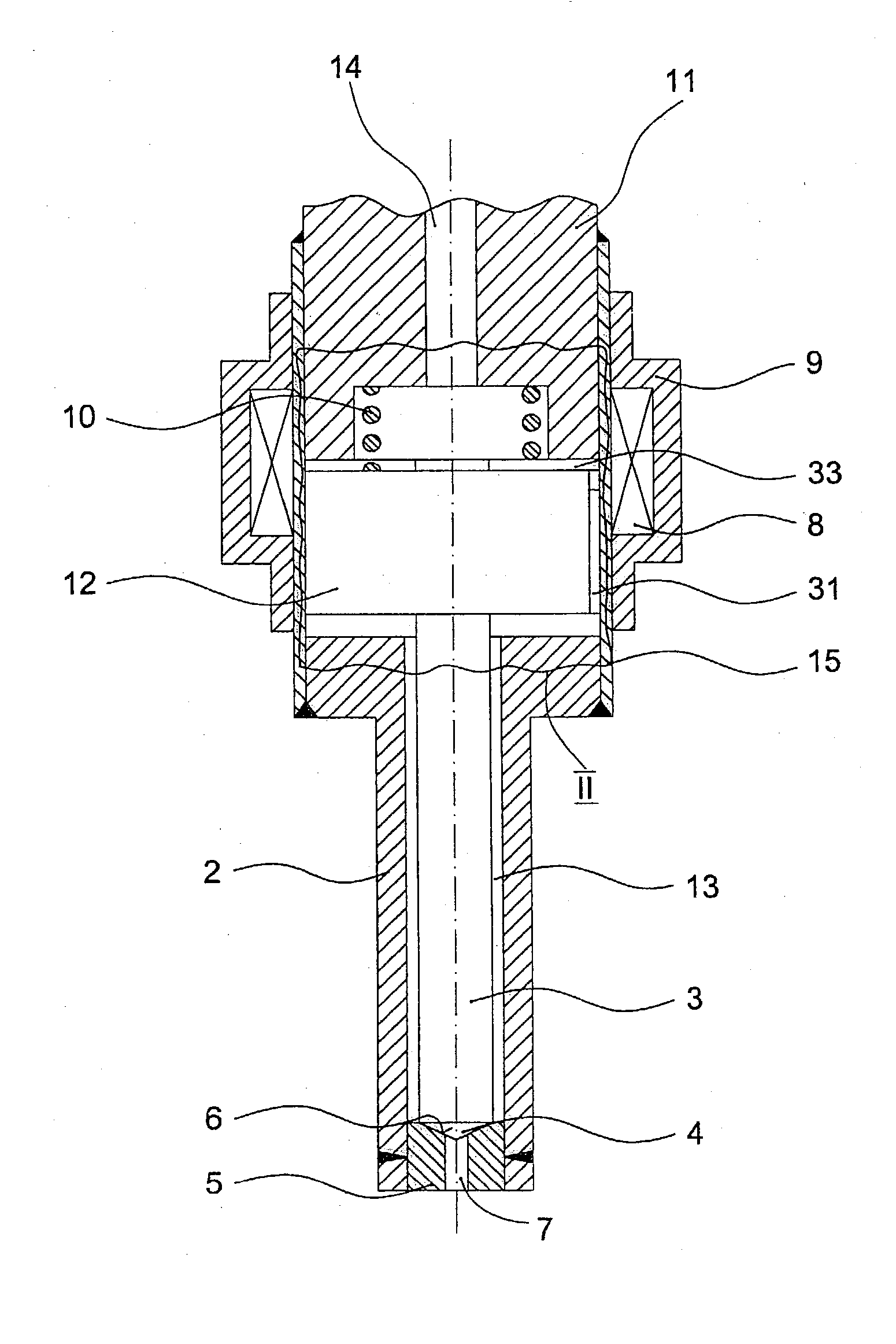
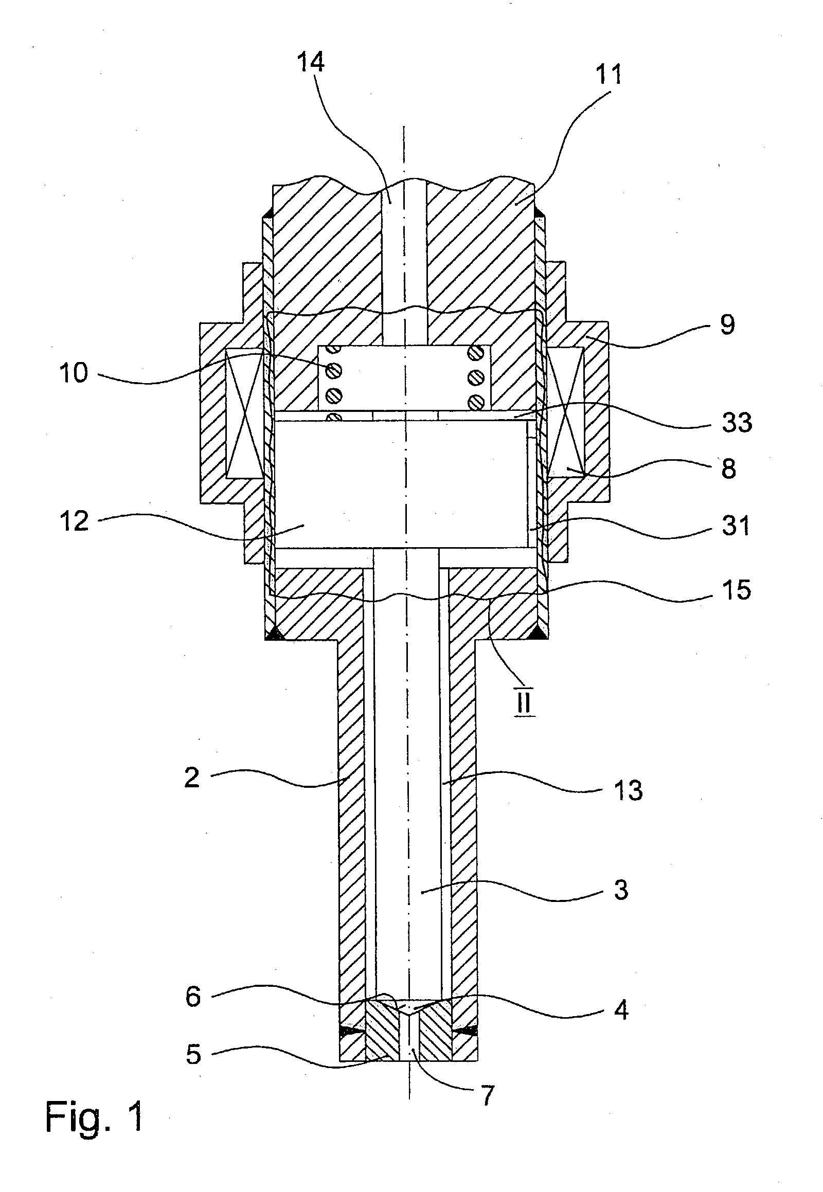
[0012] A fuel injector 1 depicted in FIG. 1 is used in particular for direct injection of fuel into the combustion chamber of an internal combustion engine having spark ignition and fuel mixture compression. Fuel injector 1 includes a solenoid 8 which is encapsulated in a coil housing 9, a tube-shaped internal pole 11 and a sleeve-shaped stationary pole 15 which is welded to a nozzle body 2. An armature 12, which is acted on by a restoring spring 10, contains at least one equalizing channel 31, through which the centrally supplied fuel is fed through a recess 13 in nozzle body 2 to the sealing seat. Armature 12 is mechanically linked to a valve needle 3, which is formed into a valve-closure member 4 in the injection direction. Valve-closure member 4 together with a valve-seat surface 6, which is formed on a valve-seat member 5, forms a sealing seat. This embodiment is an inward-opening fuel injector 1. At least one injection orifice 7 is formed in valve-seat member 5.

[0013] In the r...


PUM


Abstract

A fuel injector (1) for fuel injection systems of internal combustion engines is constructed of a solenoid (8), an armature (12) which is acted upon in a closing direction by a restoring spring (10), and a valve needle (3) which is frictionally engaged with the armature (12) to actuate a valve-closure member (4) which together with a valve-seat surface (6) forms a sealing seat. In or on the armature (12) at least a first fuel channel (37) is provided through which fuel flows, where the cross-section of the first fuel channel (37) is dependent on the axial position of the armature (12).

Description

BACKGROUND INFORMATION[0001] The present invention relates to a fuel injector according to the preamble of the main claim.[0002] An electromagnetically actuatable fuel injector is already known from German Patent Application 195 03 821 A1, in which an armature cooperates with an electrically excitable solenoid to cause the electromagnetic actuation, and the lift of the armature is transferred via a valve needle to a valve-closure member. The valve-closure member cooperates with a valve-seat surface to form a sealing seat.[0003] A disadvantage of the fuel injector known from German Patent Application 195 03 821 A1 is in particular the relatively long closing times. Delays in closing the fuel injector are caused by the adhesive forces operating between the armature and the internal pole and by the non-instantaneous decay of the magnetic field when the exciting current is turned off. This results in improvable metering times and metered quantities for the fuel.ADVANTAGES OF THE INVENTI...

Claims


Application Information

Patent Timeline
Patent Type & Authority Applications(United States)
IPC IPC(8): F02M51/08F02M51/06F02M61/16F02M61/20
CPCF02M51/0614F02M61/205F02M61/166F02M51/0671F02M61/20
Inventor BOEE, MATTHIASHOHL, GUENTHERKEIM, NORBERT
Owner ROBERT BOSCH GMBH
Learn More