Swing check backflow preventer having check valve with lever arm

a technology of check valve and lever arm, which is applied in the field of valves, can solve the problems of affecting the operation of the valve, requiring the removal of the entire valve housing, and requiring the removal of the housing cover, etc., and achieves the effects of low maintenance, low head loss, and low friction clapper mechanism

Inactive Publication Date: 2003-09-11
HILCO CAPITAL
View PDF6 Cites 16 Cited by
  • Summary
  • Abstract
  • Description
  • Claims
  • Application Information

AI Technical Summary

Benefits of technology

0011] It is another object of the invention to provide a swing check valve which has a simple, low maintenance, low friction clapper mechanism that creates low headloss.

Problems solved by technology

Such obstacles include the checking members, which remain disposed directly in the fluid path once the check valves are open.
A disadvantage to the swing check backflow preventer of the '009 patent is that when the valve requires maintenance, a cover of the valve housing must be removed and then retaining wires must be removed so that the valve assembly can be manually disengaged from the inlet and then withdrawn from the valve housing.
A disadvantage to the swing check valve of the '635 patent is that replacing the valve assembly requires that the housing cover first be removed.
The valve assembly of the '635 patent thus presents an awkward handling situation whenever the valve assembly requires assembly, replacement, or maintenance.
A disadvantage to the Regev valve is that, in order to replace any component of the valve assembly or replace the entire valve assembly itself, the entire valve housing must be removed from the fluid conduit system and replaced.
Furthermore, unlike the valves of the '009 and '635 patents, there is no valve assembly disposable within a valve housing in the Regev valve which can be removed from a fluid conduit system without removing the valve housing as required by backflow preventer regulation.

Method used


Image

  • Swing check backflow preventer having check valve with lever arm
  • Swing check backflow preventer having check valve with lever arm
  • Swing check backflow preventer having check valve with lever arm

Examples


Embodiment Construction

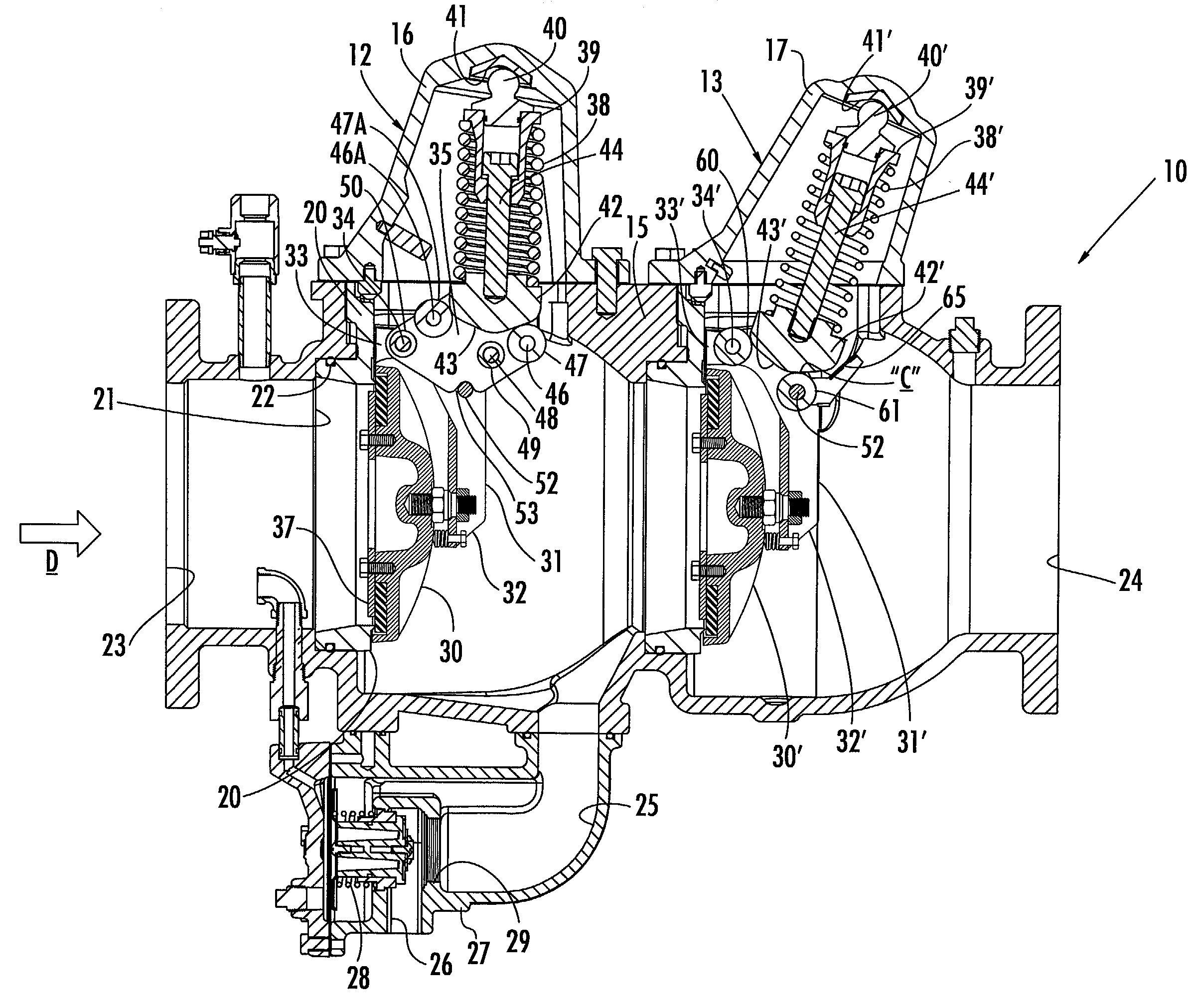
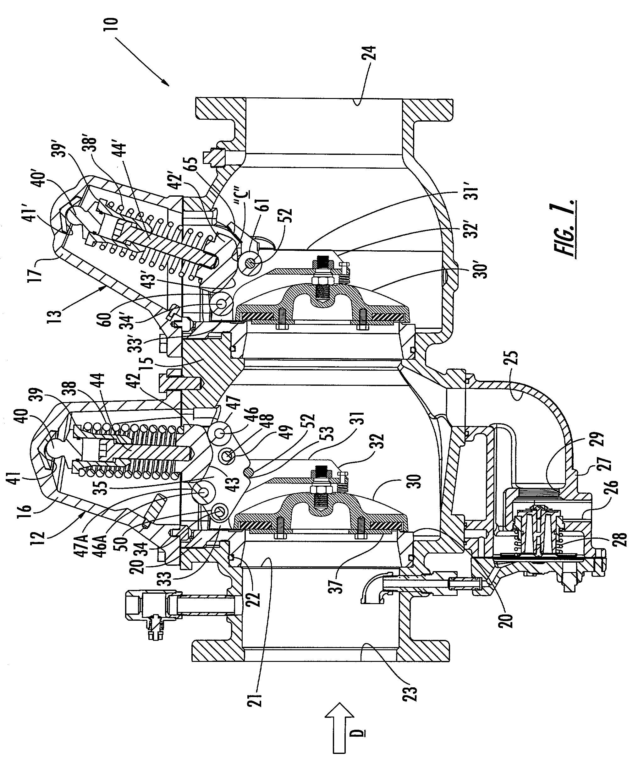
[0059] Referring now specifically to the drawings, a backflow preventer according to the present invention is illustrated in FIG. 1 and shown generally at reference numeral 10. The backflow preventer 10 includes two check valves 12 and 13 positioned in series within the same valve housing 15. Serial combination of two swing check valves in a valve housing to form a backflow preventer is well known in the art and will not be described in detail.

[0060] Regulations governing the design, manufacture, installation and maintenance of backflow preventers require that check valves and associated parts be removable for inspection and repair in the field without removing the valve housing from the waterline. The valve housing 15 thus includes two housing covers 16 and 17 removably attached by bolts 19 to the valve housing 15. Attaching the housing covers 16 and 17 in this manner permits access to the interior of the valve housing 15.

[0061] As is shown in FIG. 1, swing check valve 12 includes ...


PUM


Abstract

A swing check valve for controlling fluid flow, including a valve housing having a port for fluid flow therethrough. A valve assembly is disposed within the valve housing for controlling the fluid flow therethrough, and includes a valve seat communicating with the port. A clapper is pivotally mounted in the valve housing and moves between open and closed positions. A lever arm is pivotally mounted on the rocker arm for providing leverage against the rocker arm for positioning the clapper and rocker arm within the valve housing. A spring is captured in the valve housing, and normally urges the clapper into the closed position. A first pivot is carried by the spring for permitting unattached pivotal movement of the spring relative to the cover. A second pivot is carried by the spring for permitting the spring to pivot within the valve housing responsive to movement of the clapper.

Description

TECHNICAL FIELD AND BACKGROUND OF THE INVENTION[0001] This invention relates to a type of valve known as a "check-valve." Check valves are well known and are widely used to control backflow of fluids carrying undesirable contaminants into a fluid supply. These valves have evolved to become highly specialized in their function and operation, and are similar in that they all contain spring-loaded members that are biased toward the valve-closed position until fluid pressure acting on the checking members forces the valves open. Typically, a backflow preventer utilizes two check valves in a conventional serial combination for preventing the backflow of a fluid.[0002] The pressure required to open a check valve is established by governmental regulation and provides a minimum degree of protection against reverse flow. Furthermore, regulations governing backflow preventers require that a check valve and associated parts must be removable for inspection and field service repair without havi...

Claims


Application Information

Patent Timeline
Patent Type & Authority Applications(United States)
IPC IPC(8): F16K15/03
CPCF16K15/035Y10T137/6086Y10T137/7838Y10T137/79Y10T137/7901Y10T137/0491F16K2200/204F16K2200/101F16K27/0232F16K15/033
Inventor FUNDERBURK, ROBERT V.
Owner HILCO CAPITAL
Why Eureka
Try Eureka