Filter housing and intermediate floor

A filter and housing technology, applied in the field of filter housing, can solve the problems of pump failure, pollution, pipeline blockage, etc., and achieve the effect of simplicity, cost, low cost and low cost

Pending Publication Date: 2020-01-17
ROBERT BOSCH GMBH
View PDF10 Cites 0 Cited by
  • Summary
  • Abstract
  • Description
  • Claims
  • Application Information

AI Technical Summary

Problems solved by technology

[0003] However, a reversal of the pumping direction causes dirt particles attached to the filter module to be released and thus directed towards the pump
This can lead to clogging and / or contamination of the lines on the one hand and failure of the pump on the other hand

Method used


Image

  • Filter housing and intermediate floor
  • Filter housing and intermediate floor
  • Filter housing and intermediate floor

Examples


Embodiment Construction

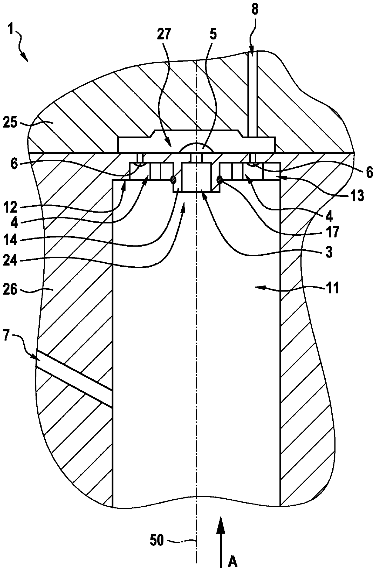
[0030] figure 1 A filter housing 1 according to an exemplary embodiment of the invention is shown schematically. The filter housing 1 comprises in particular an upper housing 25 and a lower housing 26 which can be assembled to form the filter housing 1 . It is provided here that the lower housing 26 has a receptacle 11 into which the filter module 2 can be inserted (see Figures 3 to 7 ). The receptacle 11 is hollow-cylindrical or alternatively conical, wherein the longitudinal axis 50 of the filter housing 1 is the central axis of the hollow-cylindrical shape. The longitudinal axis 50 is the axis of the filter housing 1 along which the filter housing 1 has its greatest extent. If the filter module 2 is to be inserted into the receptacle 11 , this is advantageously done by insertion along the longitudinal axis 50 .

[0031] Several directions are defined by the hollow cylindrical shape of the receptacle 11 of the filter housing 1 . Therefore, the direction specification a...


PUM


Abstract

The invention relates to a filter housing (1), comprising a receptacle (11) for holding a filter module of a vehicle, an inlet (7) for feeding unfiltered fluid to an unfiltered side (9) of the filtermodule, an outlet (8) for leading away filtered fluid from a filtered side (10) of the filter module, a passage opening (3) for establishing fluid communication between the outlet (8) and the filteredside (10) of the filter module, a bypass opening (4) for establishing fluid communication between the outlet (8) and the unfiltered side (9) of the filter module, a first non-return element (5) for selectively closing the passage opening (3), and a second non-return element (6) for selectively closing the bypass opening (4), the first non-return element (5) blocking fluid flow from the outlet (8)of the filter housing (1) to the filtered side (10) of the filter module, and the second non-return element (6) blocking fluid flow from the unfiltered side (9) of the filter module to the outlet (8)of the filter housing (1). The invention further relates to an intermediate floor for inserting between a filter module and a filter housing (1) of a vehicle, the filter module being insertable intoa receptacle (11) of the filter housing (1), the intermediate floor comprising a passage opening (3) for establishing fluid communication between an outlet (8) and a filtered side (10) of the filter module, a bypass opening (4) for establishing fluid communication between the outlet (8) and a filtered side (9) of the filter module, a first non-return element (5) for selectively closing the passageopening (3), and a second non-return element (6) for selectively closing the bypass opening (4), the first non-return element (5) blocking fluid flow from the outlet (8) of the filter housing (1) tothe filtered side (10) of the filter module, and the second non-return element (6) blocking fluid flow from the unfiltered side (9) of the filter module to the outlet (8) of the filter housing (1).

Description

technical field [0001] The invention relates to a filter housing. Furthermore, the invention relates to an intermediate base introduced between the filter module and the filter housing. A filter module, in particular a filter module for filtering fluids of a motor vehicle, is particularly advantageous for filtering fuel and / or urea solutions. Within the scope of the present invention, the terms "having" and "including" are used synonymously. Background technique [0002] A filter module is known from the prior art. Such filter modules are commonly used in vehicles in order to filter the urea solution required in the vehicle to reduce nitrogen oxide emissions. However, urea solutions can freeze at low temperatures and thus damage the ice pressure in the filter module. Therefore, it is provided in the vehicle that the entire system for injecting the urea solution is emptied when the vehicle is stationary. To do this, the pumping direction must be reversed so that the enti...

Claims


Application Information

Patent Timeline
IPC IPC(8): B01D35/147B01D35/153B01D35/16B01D35/30
CPCB01D35/147B01D35/153B01D35/16B01D35/30B01D35/306B01D2201/301B01D2201/302B01D2201/306
Inventor G·科伊森J·塞梅
Owner ROBERT BOSCH GMBH
Why Eureka
Try Eureka