Wall-mounted electric devices

a technology for electric devices and covers, which is applied in the direction of electrical apparatus casings/cabinets/drawers, electrical apparatus casings/cabinets/drawers details, electrical apparatus, etc. it can solve the problems of affecting the use of electric parts, and the support is too narrow, so as to avoid accidents to the user, reduce breakage, and resist knocks or impacts.

Inactive Publication Date: 2003-09-11
IND SICA S A I C
View PDF0 Cites 5 Cited by
  • Summary
  • Abstract
  • Description
  • Claims
  • Application Information

AI Technical Summary

Benefits of technology

0010] Some of the objects and advantages of this invention are described herein below:
0011] a) It is an object of the exemplary form of the present invention to provide a very robust set that better resists knocks or impacts, thus reducing breakage.
0012] b) It is a further object of the exemplary form of the present invention to provide a set that, in the event of breakage of the outer cover, it does not leave the electric parts exposed and avoids accidents to the user.
0013] c) It is a further object of the exemplary form of the present invention to provide a set that limits the introduction of elements such as dust, water or moist into the assembly opening.
0014] d) It is a further object of the exemplary form of the present invention to provide a set that enhances the decorative possibilities thereof, as different outer covers can be exchanged with different inner frames.
0015] e) It is a further object of the exemplary form of the present invention to provide a set that eliminates the inconveniences of the assembly openings wherein the flanges are too deep, since the electric device frame is mounted on the intermediate support that immobilizes it.

Problems solved by technology

In such conventional systems, when the outer cover breaks down, the frame of the device turns visible, thus affecting their aesthetic aspect and, what is more dangerous, leaving the electric parts exposed, with the resulting danger to the user.
The problem with these systems is that the support is too narrow and does not cover the whole assembly opening.
Consequently, when the outer cover breaks down, the electric parts are left exposed with the resulting danger.
Furthermore, all these systems present the disadvantage of having limited decorative possibilities, since in order to change their appearance, the only possible thing is to change the outer cover.

Method used


Image

  • Wall-mounted electric devices
  • Wall-mounted electric devices
  • Wall-mounted electric devices

Examples


Embodiment Construction

[0072] Preferred Embodiment

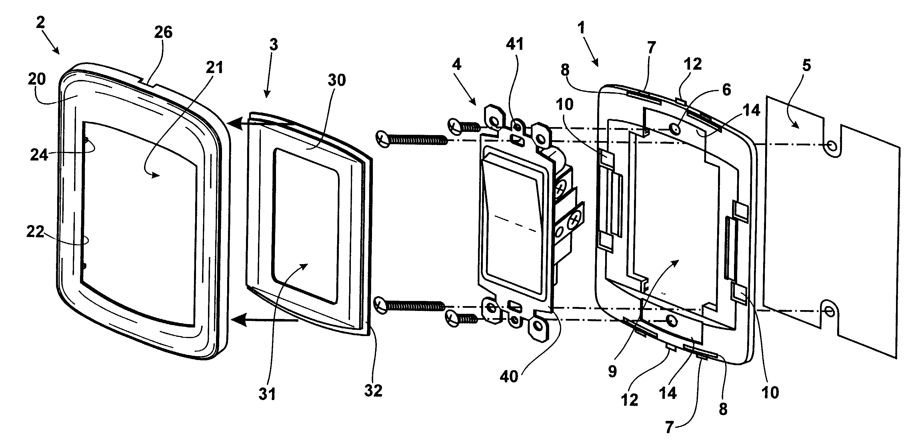
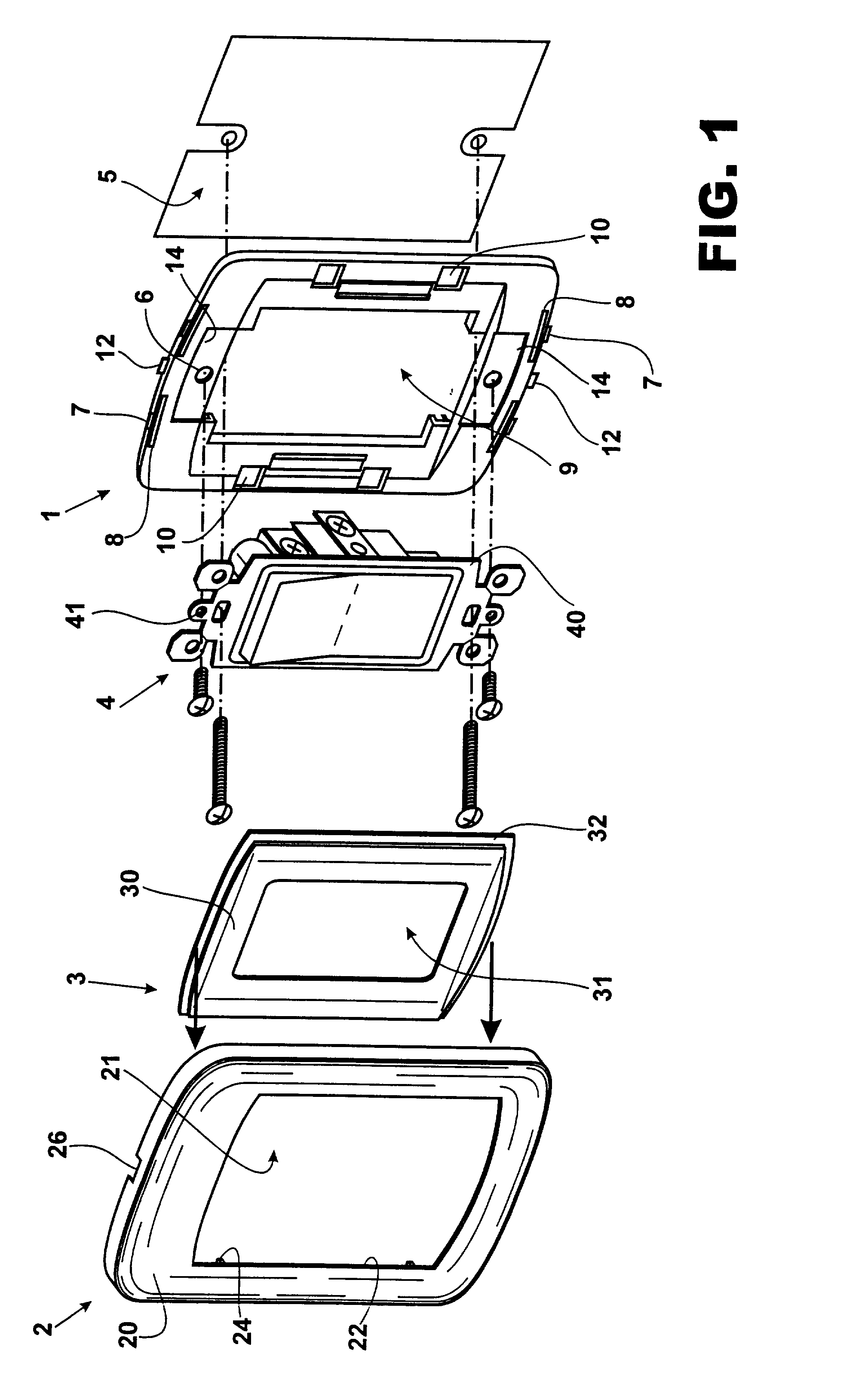
[0073] Referring now to the drawings and particularly to FIG. 1, the present invention consists of a set of cover 2 and support 1 for electric devices 4, comprising an intermediate support 1 on which the frame 40 of the electric device 4 is mounted-, and a decorative outer cover 2 with an inner frame 3, both mountable on the previously mentioned intermediate support 1.

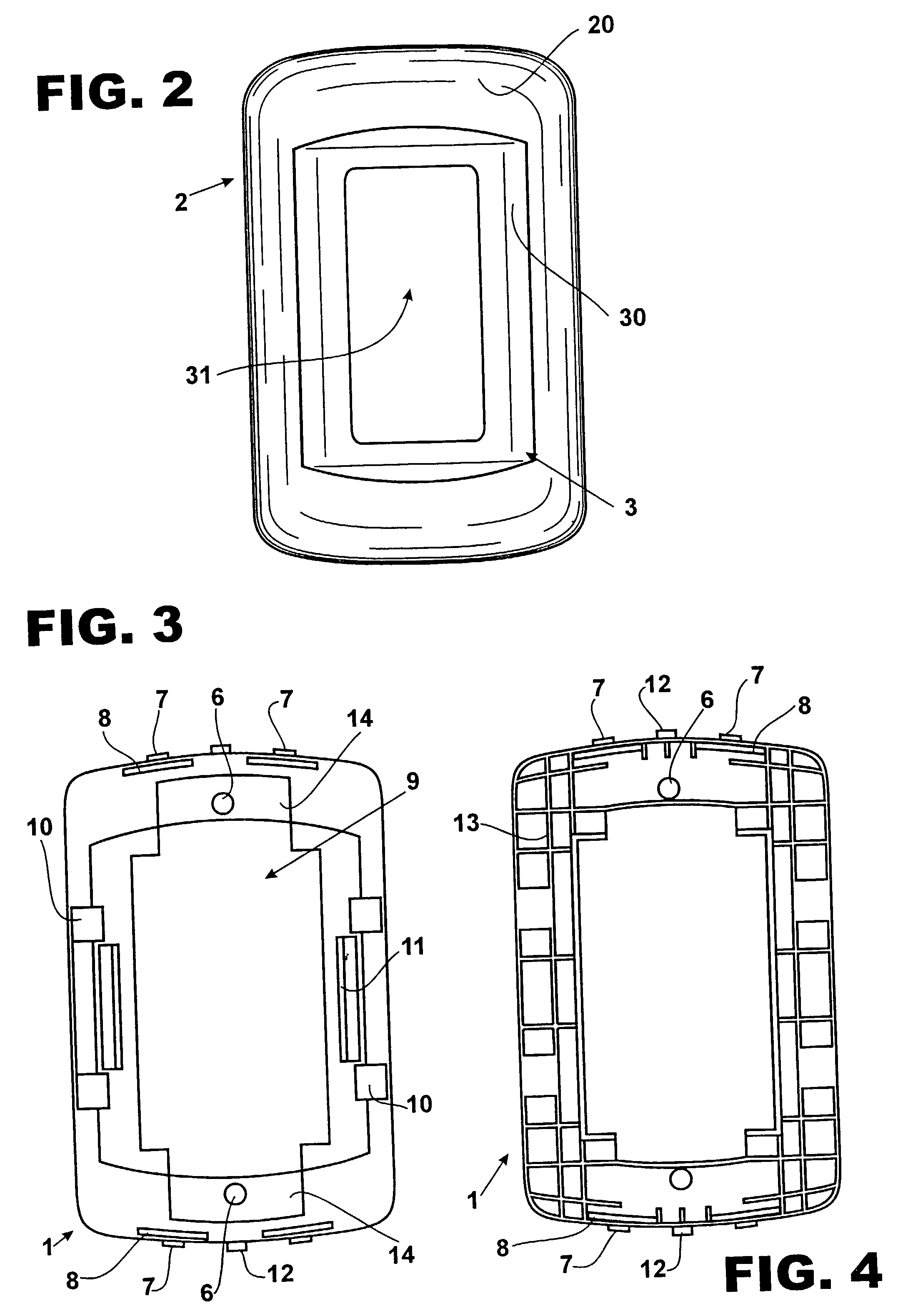
[0074] As shown in FIG. 3, the intermediate support 1 is a piece of plastic material on which the electric device 4 is mounted by means of screws. In its head ends there are cavities 14 wherein the ends of the frame 40 are inserted. The central opening 9 allows to leave the electric device 4 exposed.

[0075] In addition, in the head ends of the intermediate support 1 there are elastic engagement means 7 consisting of elastically lessening teeth, below which there are the corresponding openings with elastic backward motion 8. Also, in the head ends there are supporting projections 12 for the dis...


PUM


Abstract

A set of cover 2 and support 3 for electric devices 4 comprising an intermediate support 1-on which frame 40 of the electric device 4 is mounted-and an decorative outer cover 2 with an inner frame 3, both mountable on the previously mentioned intermediate support 1. The frame 40 of the electric device 4 is mounted on the intermediate support 1; the decorative inner frame 3 is engaged in the decorative outer cover 2. The set protects the electric device 4 and the assembly opening 5. The decorative outer cover 2 and the inner frame 3 can be independently exchanged to vary the external appearance of the set.

Description

I--BACKGROUND OF THE INVENTION[0001] 1. Technical Field[0002] This invention relates to covers for the mounting of electric devices through openings. Specifically, this invention relates to a set of cover and support that, while being applicable to electric switches and power sockets, it allows a better protection of the electric parts as well as the modification of their ornamental aspect.[0003] 2. Description of Prior Art[0004] Most of the conventional cover systems for electric devices, such as electric switches, power sockets or telephone connectors comprise an outer cover that is fixed to the frame of the device by means of screws.[0005] In such conventional systems, when the outer cover breaks down, the frame of the device turns visible, thus affecting their aesthetic aspect and, what is more dangerous, leaving the electric parts exposed, with the resulting danger to the user.[0006] Other cover systems are known in the prior art. For example, some types comprise a support and ...

Claims


Application Information

Patent Timeline
Patent Type & Authority Applications(United States)
IPC IPC(8): H02G3/14
CPCH02G3/14
Inventor WENGROWER, CESAR
Owner IND SICA S A I C
Why Eureka
Try Eureka