Valve assembly

a valve assembly and fluid dispenser technology, applied in the direction of liquid transfer devices, instruments, volume meters, etc., can solve the problems of limited dispense rate and frequent maintenance procedures, and achieve the effect of reducing fouling

Inactive Publication Date: 2003-10-02
FAST & FLUID MANAGEMENT
View PDF6 Cites 13 Cited by
  • Summary
  • Abstract
  • Description
  • Claims
  • Application Information

AI Technical Summary

Benefits of technology

0014] The diameter of the second (outlet) opening in the housing may be larger than the diameter of at least some or all of the radially extending channels

Problems solved by technology

However, the valve assembly disclosed in the '731 patent is prone to clogging and therefore can be unreliable and require frequent maintenance procedures.
Further, the valve assem

Method used


Image

  • Valve assembly
  • Valve assembly
  • Valve assembly

Examples


Embodiment Construction

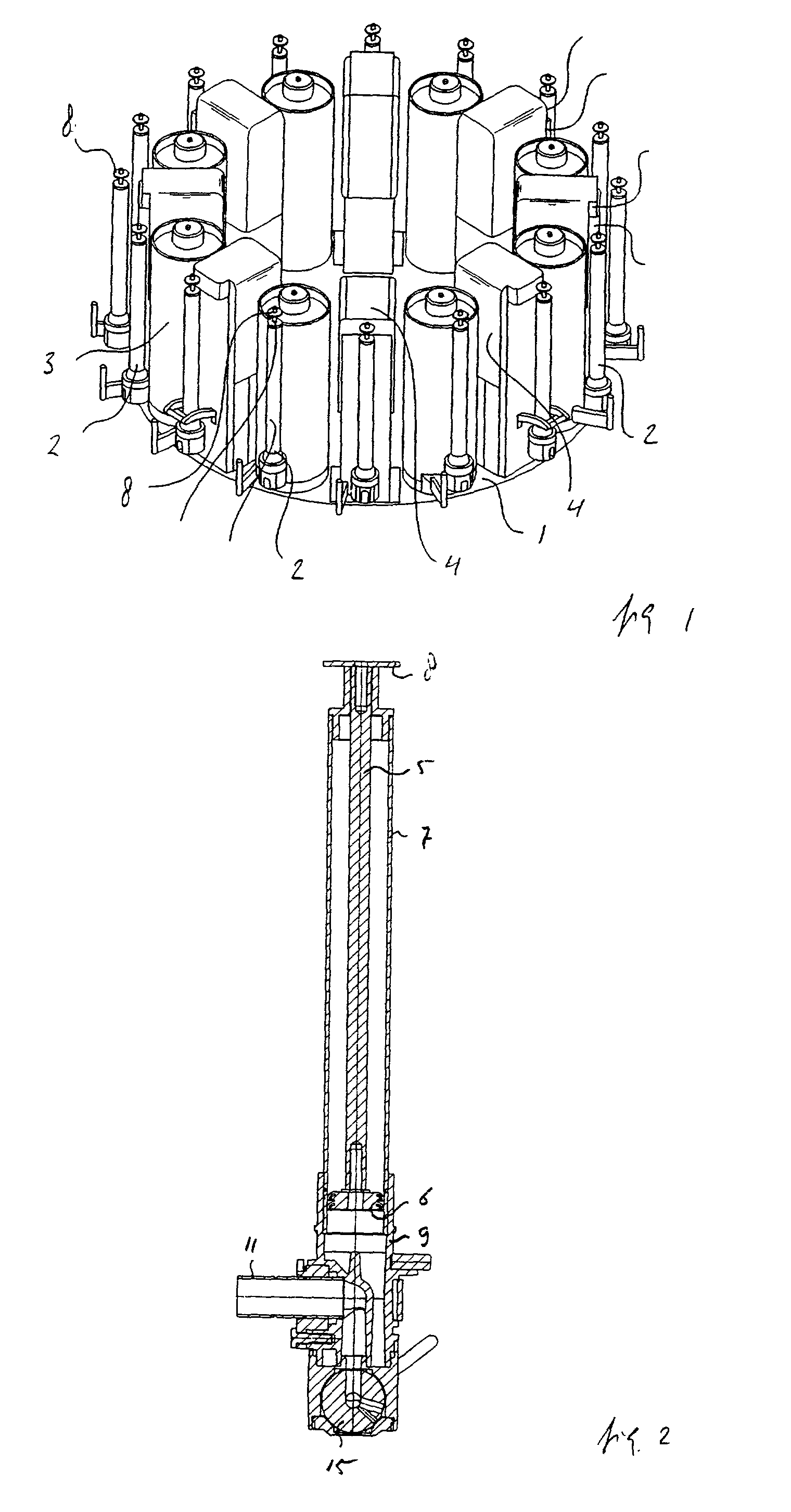
[0026] FIG. 1 illustrates the main parts of an example of an apparatus 10 for dispensing viscous fluids, such as paints or dyes. This particular dispensing apparatus is an automated version and includes a turntable 1. The turntable 1 is rotatable about a vertical axis by means of a drive (not shown) in order to rotate the turntable 1 between discrete positions.

[0027] On the turntable 1, there is mounted a plurality of pumps 2, e.g., sixteen pumps. Each pump 2 is associated with a fluid container, in this case two types of fluid containers: alternately a stationary type canister 3 and a replaceable flexible package (not shown) contained in a rigid, removable holder 4. When one of the canisters 3 is empty or nearly empty, it should be refilled by pouring fluid, such as a paint component, into it. When a flexible package is empty, the package and the holder 4 containing it can be removed. Subsequently, the holder 4 can be opened to take out the empty package and to insert a new, filled...


PUM


Abstract

A valve assembly for a fluid dispenser includes a housing having at least a first opening and a second opening, and a valve member fitted in the housing, the valve member being rotatable about an axis and comprising a first channel, extending along said axis and communicating with the first opening in the housing, and at least two outlet channels radially extending from the first channel to the circumference of the valve member, wherein each of the radially extending outlet channels can be brought in register with the second opening by rotating the valve member.

Description

TECNICAL FIELD[0001] A valve assembly for a fluid dispenser and a fluid dispenser comprising the same are disclosed.BACKGROUND OF THE RELATED ART[0002] Valve assemblies for viscous fluid dispensers are known from U.S. Pat. No. 6,003,731. FIGS. 16 and 19a-19d of the '731 patent show a pumping arrangement (117) adapted to draw fluid from a package (101) and subsequently expel the fluid in accurate dosages.[0003] However, the valve assembly disclosed in the '731 patent is prone to clogging and therefore can be unreliable and require frequent maintenance procedures. Further, the valve assembly disclosed in the '731 patent includes only one outlet opening or channel and therefore the dispensing apparatus of the '731 patent can perform at only limited dispense rates.[0004] Therefore, there is a need for an improved valve assembly for liquid dispensers which are more reliable, require less maintenance and which are capable of dispensing at slower, more accurate dispense rates and faster di...

Claims


Application Information

Patent Timeline
IPC IPC(8): B67D7/06B67D7/04F16K11/087
CPCF16K11/0876
Inventor VOSKUIL, MARK M.J.ALKEMADE, PIETER J.M.
Owner FAST & FLUID MANAGEMENT
Why Eureka
Try Eureka