Method and apparatus for tie-point registration of disparate imaging sensors by matching optical flow

a technology of optical flow and imaging sensor, applied in the field of imaging systems, can solve the problems of practical limitations and limited methods of tie-point selection

Inactive Publication Date: 2003-10-30
THE UNITED STATES OF AMERICA AS REPRESENTED BY THE SECRETARY OF THE NAVY
View PDF6 Cites 18 Cited by
  • Summary
  • Abstract
  • Description
  • Claims
  • Application Information

AI Technical Summary

Problems solved by technology

This method is limited by the accuracy of tie-point selection, as well as b

Method used


Image

  • Method and apparatus for tie-point registration of disparate imaging sensors by matching optical flow
  • Method and apparatus for tie-point registration of disparate imaging sensors by matching optical flow
  • Method and apparatus for tie-point registration of disparate imaging sensors by matching optical flow

Examples


Embodiment Construction

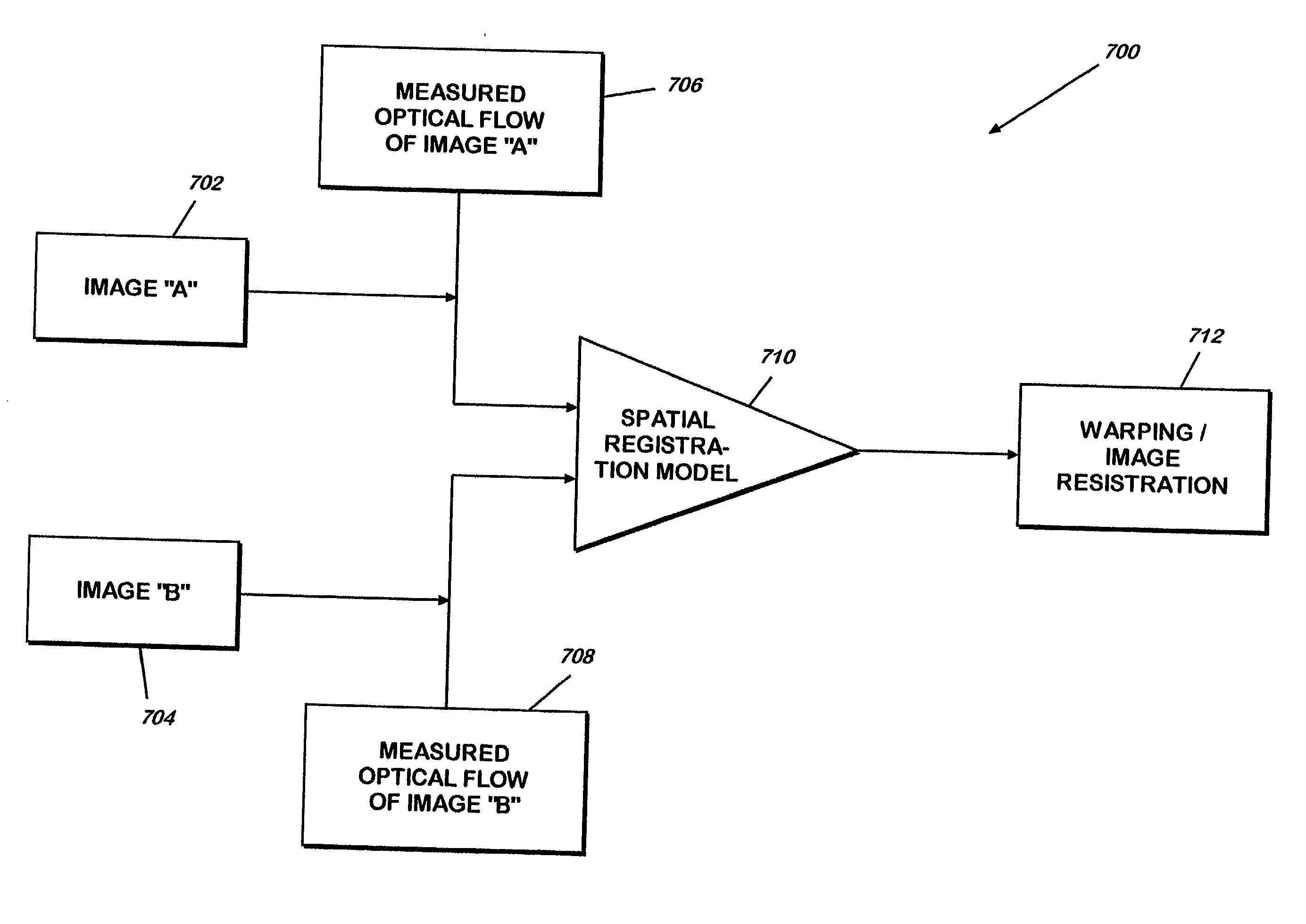
[0032] Referring now to FIG. 7, there is shown a schematic illustrating registration of images A and B by matching optical flow in accordance with an exemplary embodiment of the present invention. FIG. 7 identifies a similar set of tie-points in image A at 702 as those that are identified in image A depicted at 602 (FIG. 6). Likewise, a similar set of tie-points in image B is identified at 704. Subsequently, the optical flow of images A and B is measured at 706 and 708, respectively. The optical flow is defined as a description of how every pixel moves in a video sequence relative to some reference frame. Optical flow may be determined using a variety of means. For example, a camera may be moved or displaced around an object and the correlation between one frame and a subsequent frame in an image may be determined, whose well defined surface peak corresponds to the displacement between the two images A.sub.0 and A.sub.1. This is one exemplary approach to determine optical flow betwe...


PUM


Abstract

A method and apparatus for enabling the registration of co-located, disparate imaging sensors by computing the optical flow of each sensor as all the sensors simultaneously observe a moving object, or as all the sensors simultaneously move observing an object. The tie point registration of disparate imaging sensors is made more robust by matching optical flow and by levering the temporal motion within a pair of video sequences and using an additional constraint to minimize the disparity in optical flow between registered video sequences. The method includes parametrically computing the optical flow of each video sequence separately relative to a reference frame pair, identifying a matching constellation of tie-points in the reference pair of images, for all frames, computing the positions of tie-points bi=b0+ei where ei=predictive term to generate a new set of tie-points, after transformation by optical flow. For each frame, the total squared error resulting from an over-determined solution of affine registration problem is computed. The choice of ei is adjusted to minimize the total squared error over all frames of video.

Description

[0001] 1. Field of the Invention[0002] This invention relates to imaging systems, and more particularly, to a robust method for tie-point registration of disparate imaging sensors by matching the optical flow contained in the temporal motion within a pair of video sequences. This is achieved by minimizing the disparity in optical flow between registered video sequences.[0003] 2. Description of Related Art[0004] Image registration techniques play an important role in terrain assessment, mapping, and sensor fusion. A majority of the imaging systems include a combination of distinct electro-optical sensors that are constrained to view the same scene through a common aperture or from a common platform. Most often, a spatial registration of one sensor's image is required to conform to the slightly disparate imaging geometry of a different sensor on the same platform. The spatial registration is generally achieved through a judicious selection of image tie-points and a geometric transform...

Claims


Application Information

Patent Timeline
IPC IPC(8): G06T7/00G06V10/24
CPCG06K9/32G06T7/0038G06T7/0028G06T7/33G06T7/38G06V10/24
Inventor SCHULER, JONATHON
Owner THE UNITED STATES OF AMERICA AS REPRESENTED BY THE SECRETARY OF THE NAVY
Why Eureka
Try Eureka