Optical branching circuit and device

a branching circuit and optical technology, applied in the direction of optics, optical waveguide light guides, instruments, etc., can solve the problems of deteriorating affecting the branching characteristic of the optical branching circuit, and causing the variation of the branching characteristi

Inactive Publication Date: 2003-10-30
TDK CORPARATION
View PDF3 Cites 11 Cited by
  • Summary
  • Abstract
  • Description
  • Claims
  • Application Information

AI Technical Summary

Problems solved by technology

By the way, in an actual optical branching circuit, there has been a problem that even if the shape is the same, variation in branching characteristics occurs.
Besides, in the case where an optical branching circuit is connected to the front stage as well, there has been a problem that light generated at a branching portion and not coupled with the waveguide mixes in the latter stage optical br...

Method used


Image

  • Optical branching circuit and device
  • Optical branching circuit and device
  • Optical branching circuit and device

Examples


Embodiment Construction

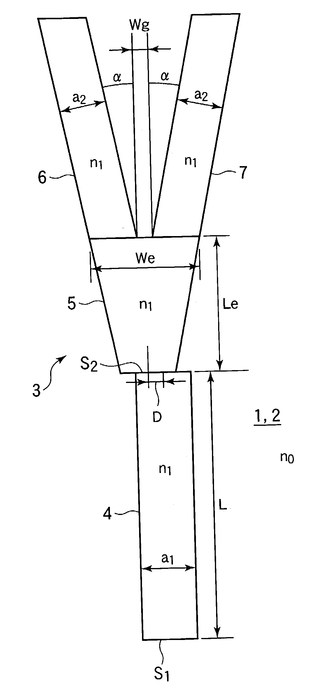
[0035] Next, a concrete example will be described. First, a specific refractive index difference .DELTA.n between a core and a clad was made .DELTA.n=0.4%. As the structure of the optical branching circuit, the width of the incident optical waveguide 4 was a.sub.1=7 .mu.m, the length of the tapered optical waveguide 5 was Le=180 .mu.m, and the width of the end face was We=15 .mu.m. The gap width was Wg=1 .mu.m, the width of each of the branching optical waveguides 6 and 7 was a.sub.2=7 .mu.m, and the branching angle was .alpha.=0.4.degree..

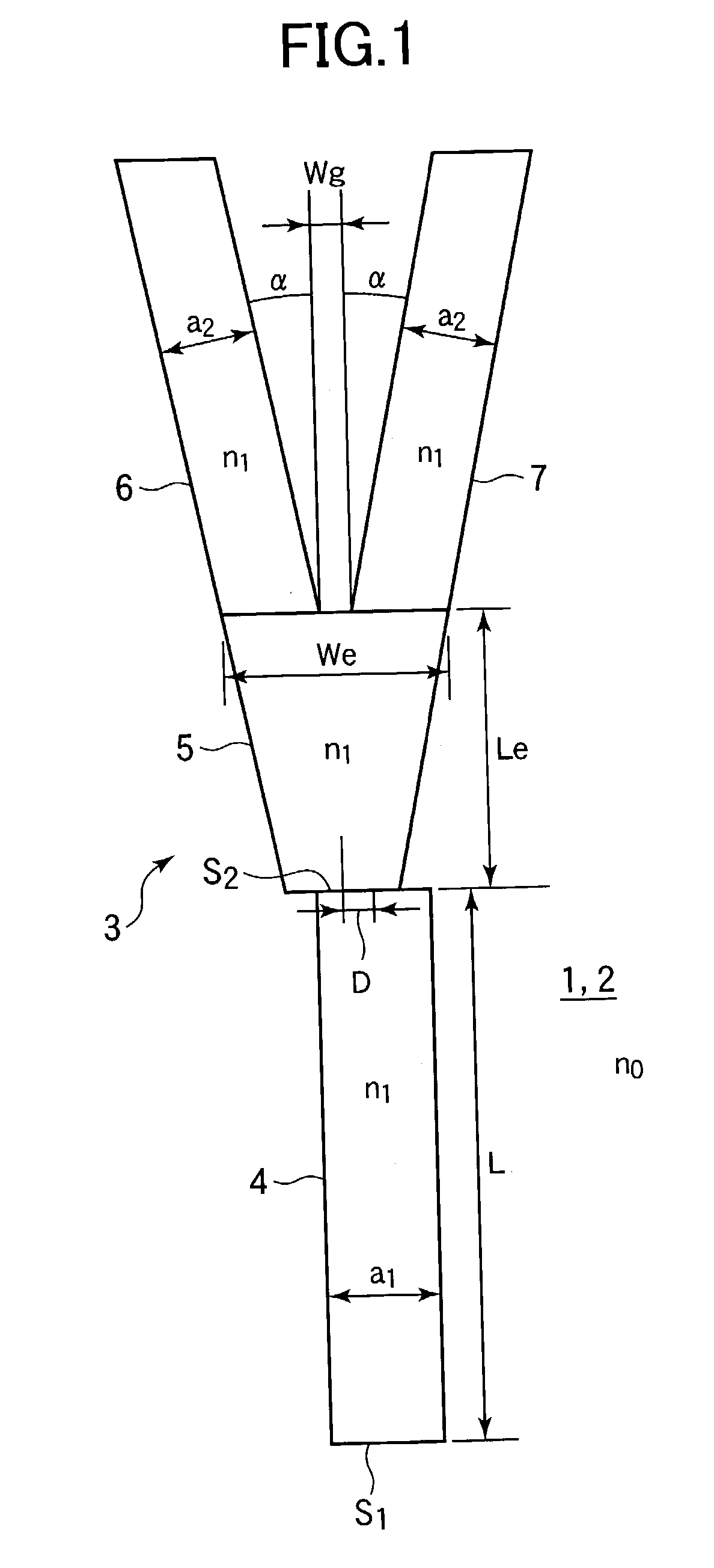
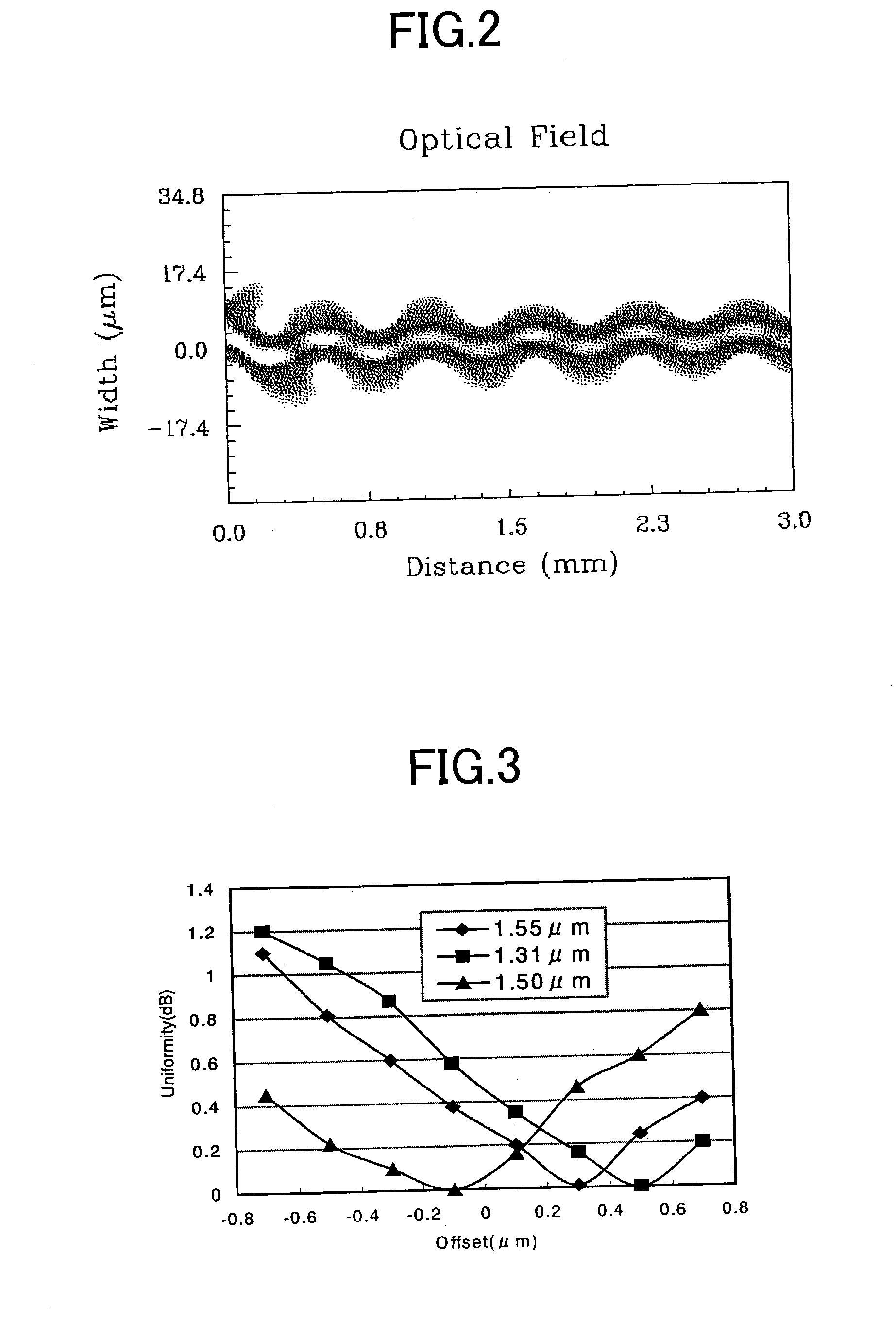
[0036] The calculation of a loss (output light power / input light power) between the input and output ports was made by the BPM (beam propagation method). In order to calculate the influence of leaky light, an initial excitation light distribution was made a Gaussian shape, and an offset was given to the center axis of the optical waveguide to intentionally generate a mode mismatching loss. With respect to the branching characteristic, a difference...


PUM


Abstract

The invention relates to an optical branching circuit connected to a light output end face of an optical waveguide circuit or an optical branching circuit and for branching input light, and has a feature to provide an optical branching circuit with less branching ratio variation. The optical branching circuit is comprised of an input optical waveguide formed on a silica glass substrate and for outputting input light inputted from a light input end face to a light output end face, a tapered optical waveguide disposed to be shifted with respect to the input optical waveguide at the light output end face, and branching optical waveguides connected to a light output end face of the tapered optical waveguide at a predetermined branching angle.

Description

[0001] 1. Field of the Invention[0002] The present invention relates to an optical branching circuit and device connected to a light output end face of an optical waveguide circuit or an optical branching circuit and for branching input light.[0003] 2. Description of the Related Art[0004] A general optical branching circuit is comprised of an input optical waveguide, a taper-shaped transition region (tapered optical waveguide) for adiabatically changing a light distribution, and respective branching optical waveguides.[0005] Although the optical branching circuit is designed so that optical powers propagated to the respective branching optical waveguides have a desired value (branching ratio), a measured value of an actually fabricated optical branching circuit often becomes a value different from a calculated branching ratio. For example, an optical power propagated to each of the branching optical waveguides is determined by the overlap degree of a light electric field distributio...

Claims


Application Information

Patent Timeline
IPC IPC(8): G02B6/12G02B6/122G02B6/125G02B6/132
CPCG02B6/1228G02B2006/12195G02B6/132G02B6/125
Inventor HANASHIMA, NAOKI
Owner TDK CORPARATION
Why Eureka
Try Eureka