Fuel cell system and method for voltage monitoring for a fuel cell system

a fuel cell and voltage monitoring technology, applied in the field of fuel cell systems, can solve the problems of affecting the operation of the fuel cell unit, and reducing the required space, so as to reduce the required space, and protect the system from failures.

Inactive Publication Date: 2003-12-11
DAIMLER AG
View PDF0 Cites 19 Cited by
  • Summary
  • Abstract
  • Description
  • Claims
  • Application Information

AI Technical Summary

Benefits of technology

[0009] The fuel cell system according to the invention has a voltage monitoring unit of a redundant configuration and which contains at least two voltage monitoring units. The advantage of a redundant voltage monitoring system is its robustness against faults. If one of the voltage monitoring units is operating incorrectly, then it is possible to make use of the other voltage monitoring unit. A further advantage is that the voltage monitoring units themselves diagnose faulty behaviour in one another by continuously comparing voltage actual values, in particular measured values and / or estimated values.
[0010] Furthermore, there is no need for a diode, as is normally provided in the cables which connect the fuel cell unit to the corresponding electrical components, in order to prevent any current from flowing into the fuel cell unit. This leads to a relatively large amount of weight being saved since this type of diode normally has a, precharging apparatus, cooling and a housing, which weighs several kilograms. Furthermore, without the diode there is a reduction in the required space.

Problems solved by technology

However, if the current flow direction were to change with electrical current flowing into the fuel cell unit, for example due to faulty operation, then this can lead to damage, or in the extreme even to destruction, of the fuel cell unit.
Faulty operation such as this occurs, for example, when a voltage which is greater than the no-load voltage of the fuel cell unit is applied to the output terminals of the fuel cell unit.
This leads to a relatively large amount of weight being saved since this type of diode normally has a, precharging apparatus, cooling and a housing, which weighs several kilograms.

Method used


Image

  • Fuel cell system and method for voltage monitoring for a fuel cell system
  • Fuel cell system and method for voltage monitoring for a fuel cell system

Examples


Embodiment Construction

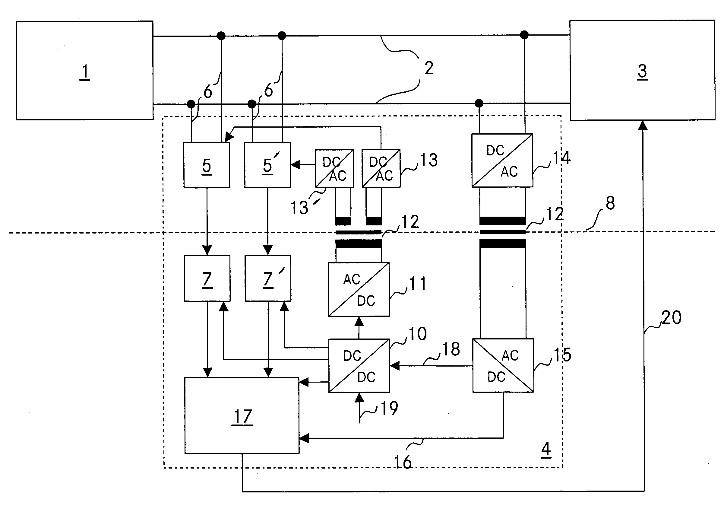
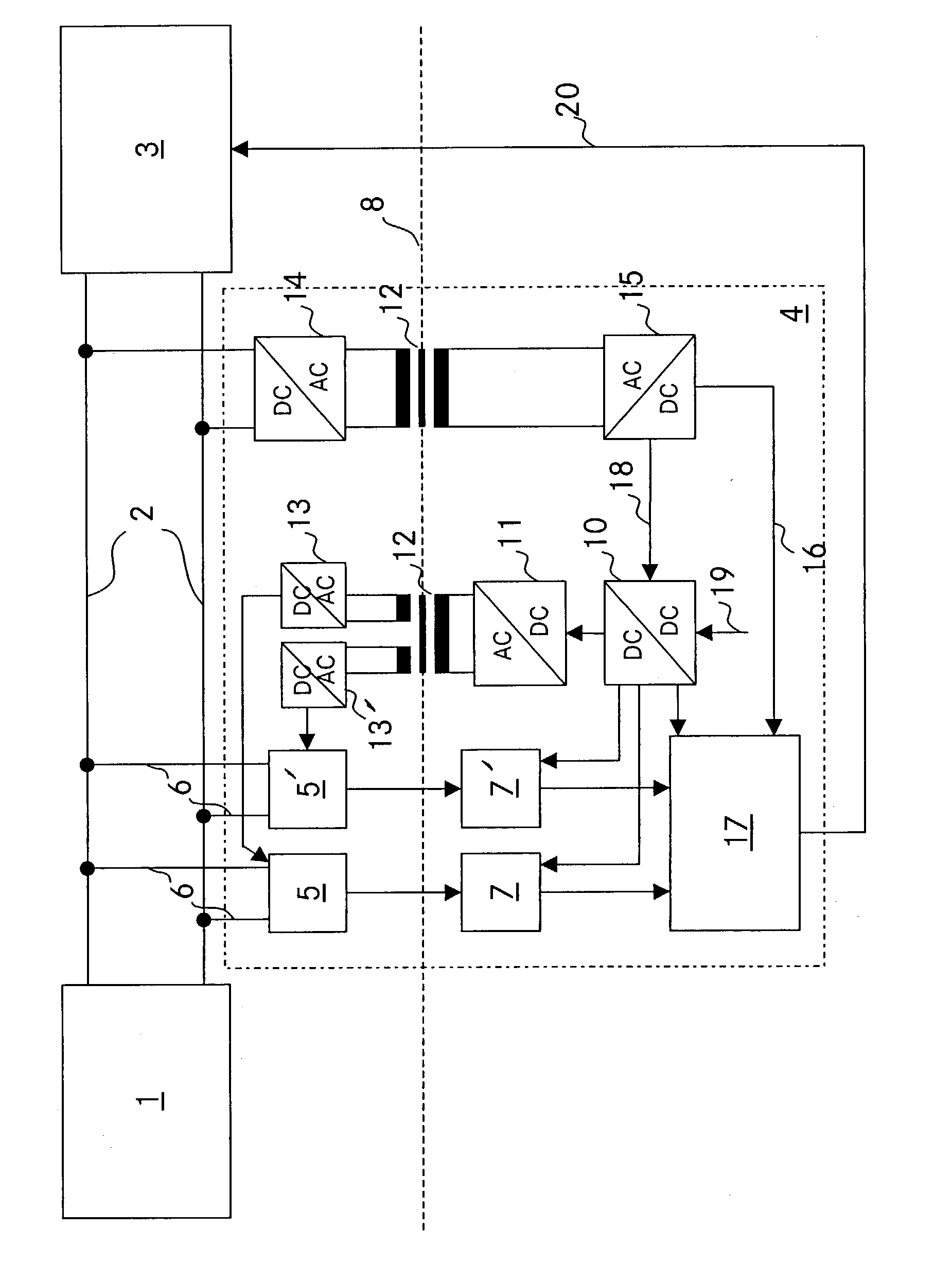
[0013] The single FIGURE shows a fuel cell system having a fuel cell unit 1, with an electrical component 3 being connected via cables or the circuit 2 to outputs, which are not shown in any more detail, of the fuel cell unit 1. One of the cables 2 is normally at a high potential, while the other of the cables 2 is at a potential that is lower than the high potential. The cables 2 are preferably high-voltage or medium-voltage cables. The fuel cell unit 1 is composed of one or more series-connected fuel cells. The taps or outputs, which are not identified in any more detail, and which are connected to cables 2 may be located between individual cells, or at the input of a first cell and at the output of a last cell. That is, the voltage is tapped off across all the series-connected and / or parallel-connected fuel cells.

[0014] The electrical component 3 is preferably operated at high voltage or medium voltage. In normal use of the terminology, the voltage which the fuel cell unit 1 supp...


PUM

PropertyMeasurementUnit
voltageaaaaaaaaaa
voltageaaaaaaaaaa
voltageaaaaaaaaaa

Abstract

A fuel cell system having a redundant voltage monitoring system for monitoring the voltage which is present on a fuel cell unit, and a method for voltage monitoring.

Description

BACKGROUND AND SUMMARY OF THE INVENTION[0001] This application claims the priority of German Patent Document No. 102 18 669.3-45, filed Apr. 26, 2002, the disclosure of which is expressly incorporated by reference herein.[0002] The invention relates to a fuel cell system having a fuel cell unit, and to a method for voltage monitoring for a fuel cell system having a fuel cell unit.[0003] Germany Patent DE 198 27 880 C1 discloses a circuit device for a fuel cell unit, by means of which the individual fuel cells can be bridged in the form of a low-impedance parallel circuit. Furthermore, a method for operating such a circuit arrangement is disclosed, with the fuel cells being bridged when the magnitude of their voltage falls below a specific threshold value, or when the mathematical sign of their voltage has changed from that during normal operation, or else when the overall fuel cell system is intended to be discharged.[0004] A method for monitoring one or more cells in a fuel cell un...

Claims


Application Information

Patent Timeline
Patent Type & Authority Applications(United States)
IPC IPC(8): G01R31/36H01M8/00H01M8/04H02H7/122H02H7/18
CPCG01R19/16542Y02E60/50H01M8/04567H01M8/04559
Inventor GEORGII, MARTIN
Owner DAIMLER AG
Why Eureka
Try Eureka