Connection admission control based on bandwidth and buffer usage

a bandwidth and buffer usage technology, applied in the field of telecommunications, can solve the problems of leaking bucket, burst information of leaky bucket, and ineffective bandwidth methods,

Inactive Publication Date: 2004-03-04
TELEFON AB LM ERICSSON (PUBL)
View PDF21 Cites 23 Cited by
  • Summary
  • Abstract
  • Description
  • Claims
  • Application Information

AI Technical Summary

Problems solved by technology

The effective bandwidth methods are often restricted to a certain type of traffic sources.
Using the asymptotic Markov-type results on leaky bucket traffic will completely loose the leaky bucket burstiness information.
Using the leaky bucket results with a Markov source does not work because they rely on the limited burst size.
Finding the point (s,t) which optimizes the approximation to the probability of loss with the actual buffer size limit, service, and traffic, in real time is generally not feasible.
If some, but not all, of the conditions are satisfied, the algorithm cannot make a determination, and therefore, does not admit the traffic.
If it is desired to widen the tolerance against deviations from the design mix, such may be possible by choosing a working point that is not optimal for the design traffic mix.
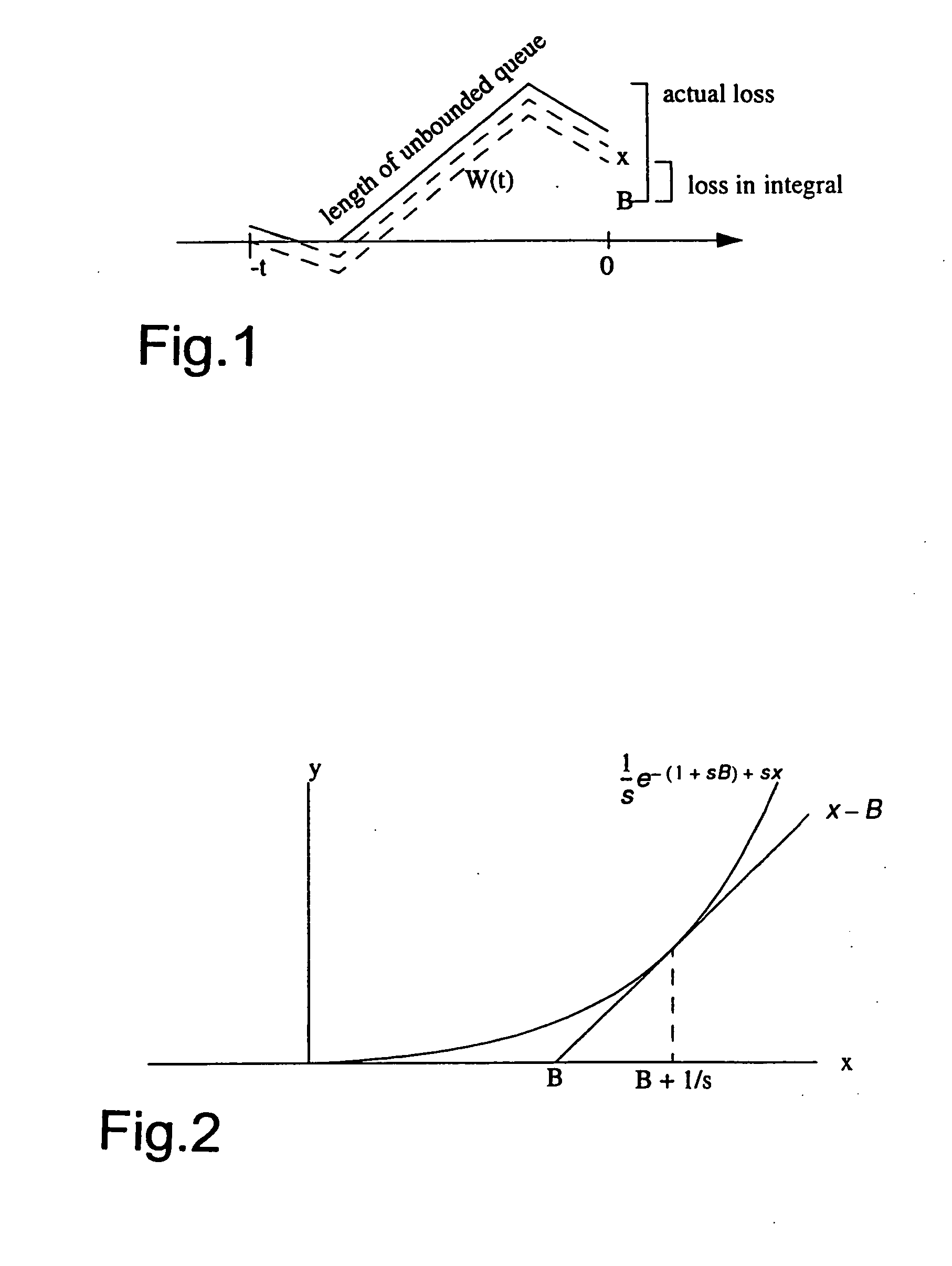
If the workload exceeds the buffer size, the excess amount of work, W(t)-B, gets lost.
This condition has not had any practical significance in the examples tested.
Unfortunately, this simple condition excludes the results with constant arrival rate and constant servi...

Method used


Image

  • Connection admission control based on bandwidth and buffer usage
  • Connection admission control based on bandwidth and buffer usage
  • Connection admission control based on bandwidth and buffer usage

Examples


example 1

5.1 Example 1

Constant Arrival Rates

[0234] The workload in an interval of length t is

A(t)=Rt

[0235] where R is the arrival rate. The log moment generating function (illustrated in FIG. 8A, for constant rate source with R=1) and its derivative with respect to s (illustrated in FIG. 8B) and its derivative with respect to t (illustrated in FIG. 8C) are 42 A( s ; t ) = log - .infin. .infin. sx ( x - Rt ) x = sRt s A( s ; t )= Rt t A( s ; t )= sR 2 s 2 A( s ; t )= 0 2 s t A( s ; t )= R 2 t 2 A( s ; t )= 0

[0236] In this case, the asymptotic approximation is exact:

.mu..sub.A(s;t)=h.sub.A(s)t

where h.sub.A(s)=s.sub.R

[0237] The approximation with constant service rate C become 43 log P lossq whereq = - log ( Rst ) and B = 0 and C = R - 1 st for s , t > 0 and 1 stR q max

[0238] This is the case where the bound applies with equality, since f.sub.W(x;t) consists of a single delta-impulse at x=(R-C)t=B+1 / s, where the exponential curve touches the line y=x-B. In this case, the approximation is exact....

example 2

5.2 Example 2

ON-OFF Periodic Fluid Source

[0239] The source is ON for T.sub.on and OFF for T.sub.off. The period is T.sub.on+T.sub.off=T. In the ON state, the source generates data at the peak rate 44 R T T on,

[0240] and in the OFF state, it generates no data. This is an extreme behavior acceptable by a leaky bucket regulator with mean rate limit R, and bucket size RT.sub.off. The phase of this periodic pattern is uniformly distributed in [0,T).

[0241] FIG. 9 is a graph showing ON-OFF periodic arrivals. In FIG. 9, A(.tau.,t+.tau.) is the amount arriving in [.tau.,t+.tau.). The phase .tau. is uniformly distributed in [0, T.sub.on+T.sub.off). From FIG. 9, it can be seen that the density function of A is the sum of two delta-impulses and a uniform distribution between them. 45 f A( x ; t ) = { ( x - nRT ) for t = nT a ( x - x 1 ) + bU ( x ; x 1 , x 2 ) + c ( x - x 2 ) otherwise where U ( x ; x 1 , x 2 ) = { 1 x 2 - x 1 for x 1 < x < x 2 0 elsewhere

[0242] For t equal to an integer number ...

example 3

5.3 Example 3

Discrete Periodic Arrivals

[0249] An amount of RT arrives at times t=nT+.alpha.T, where n is integer and .alpha..epsilon. [0,1) is constant. The phase .alpha.T is uniformly distributed in [0,T).

[0250] In an interval of length t=nT+.alpha.T arrives an amount A(t) of either (n+1)RT or nRT,

P(A(nT+.alpha.T)=nRT)=1-.alpha.

P(A(nT+.alpha.T)=(n+1)RT)=.alpha.

[0251] The log moment generating function, its derivatives, and the asymptotic log moment generating functions are 84 A( s ; nT + T) =sR ( n + 1 )T + log (( 1 - ) - sRT+ s A( s ; nT + T)= R ( n + 1 )T -RT ( 1 - ) - sRT ( 1 - ) - sRT+ t A( s ; nT + T) = 1 T 1 -- sRT ( 1 - ) - sRT+ 2 s 2 A( s ; nT + T)= R 2 T 2( 1 - ) - sRT (( 1 - ) - sRT+ ) 2 2 t s A( s ; nT + T)= R - sRT (( 1 - ) - sRT+ ) 2 2 t 2 A( s ; nT + T)= -( 1 --sRT) 2 T 2(( 1 - ) - sRT+ ) 2 h A( s ) = sR

[0252] Notice that the asymptotic log moment generating function is the same as for a constant rate process. Using this, the asymptotic log moment generating function ...


PUM


Abstract

A connection admission control (CAC) technique for a telecommunications node approximates probability of loss using a log moment generating function and its two partial derivatives of workload on a queue over a time interval. The approximation uses four state variables, which depend on the log moment generating function and its two partial derivatives. The four state variables are: (1) Linear term in approximation to log loss ratio at a working point; (2) the argument of logarithmic term in approximation to log loss ratio at the working point; (3) a buffer limit used at the working point; and (4) a multiplier of imaginary traffic used at the working point. Advantageously, these state variables vary linearly with the traffic, so a new connection can simply add its contributions to them. The connection admission control (CAC) uses the state variables to produce the following three parameters: (1) an approximation q=z-log(c) to the logarithm of the probability of loss; (2) a buffer size limit B; and (3) a multiple m of imaginary traffic from a design mix. The traffic on all connections is admissable if four conditions are satisfied. The present invention applies, e.g., to a single queue and server, and can be generalized to multiple queues and servers.

Description

[0001] 1. Field of the Invention[0002] The present invention pertains to telecommunications, and particular to connection admission control aspects of telecommunications traffic management.[0003] 2. Related Art and Other Considerations[0004] In telecommunications, traffic management is the art of providing users with the service they need and have paid for. One aspect of traffic management, connection admission control (CAC), checks to ensure that resource consumption of new connections will not violate the quality of service (QOS) requirements of new and existing connections before admitting the new connections on the network. Relevant resources involved in connection admission control (CAC) are channel numbers, bandwidth, and buffer space.[0005] Within connection admission control (CAC), effective / equivalent bandwidth methods are based on the asymptotic behavior of a tail of a queue length distribution. The algorithms of such methods calculate an effective bandwidth based on the t...

Claims


Application Information

Patent Timeline
IPC IPC(8): H04L12/56H04Q11/04
CPCH04L12/5601H04L12/5602H04L49/106H04L2012/5629H04Q11/0478H04L2012/5679H04L2012/5681H04L2012/5684H04L2012/5651
Inventor HORLIN, DANPETERSEN, LARS-GORAN
Owner TELEFON AB LM ERICSSON (PUBL)
Why Eureka
Try Eureka