3 Dimensional image projector and holodeck

a projector and image technology, applied in the field of image display devices, can solve the problems of difficult to display the 3 dimensional object or image in real time (run time) by multiple users, difficult to change the image in real time, and difficult to show the 3 dimensional virtual image in spa

Inactive Publication Date: 2004-03-11
LUMY
View PDF0 Cites 60 Cited by
  • Summary
  • Abstract
  • Description
  • Claims
  • Application Information

AI Technical Summary

Problems solved by technology

In the conventional way, it was difficult to display the 3 dimensional object or images in real time (run time) by viewed by the multiple users without special glasses in the space only by light.
Also, holograms are showing 3 dimensional image, but these images are difficult to be changed in real time (run time).
Also, the method to project the 2 dimensional image to rotating plate to create 3 dimensional image are difficult to show the 3 dimensional virtual images in the space only by light.
Also, the method to project the 2 dimensional image to semi-transparent plates to create 3 dimensional image are difficult to show the 3 dimensional virtual images in the space only by light.
But, this one is rotating fast; this is not too safe to users.
And therefore, it is not suitable for user to touch the 3 dimensional image.
Also, this by itself is almost impossible to show the image in the space only by light.
Also, users cannot touch to the 3D image in this method.
Also, even when a viewer likes to see background sight through the object, a screen stops the background sight and the viewer could not see the back ground sight.
Also, there was a problem such that the movement of back and force in slider-crankshaft-wheel system is harmonic so that the panel movement in space in time was not equally spaced, therefore, the 3D image doesn't become proportional if image is displayed in a constant timing.
But in this method, it can display only previously made 3D images only or it is not fast enough for users to interact.
This is a problem when users try to interact with 3D images.
Also, there was a problem such that when the 2D image was projected a screen, 3D image is too light for viewer to see especially in bright environment since the projection of optic 2D picture image on screen gives light image.
But user still cannot touch to the 3D image.
Also, coupling (intersecting) two light beams is difficult and expensive in many cases since it need to use more direction specifying device such as galvanometers.
Also, it is difficult and expensive to create big crystal used in these methods.
Also, these methods do not show how to make full color 3D image.
But this device by itself would be unsuitable to show the real time (run time) 3 dimensional image.
But there is not clear description of how to find the identical point in 2 dimensional images that is difficult to practice.
(Also putting higher power of beam can solve the problem, but this is usually more expensive to do.)

Method used


Image

  • 3 Dimensional image projector and holodeck
  • 3 Dimensional image projector and holodeck
  • 3 Dimensional image projector and holodeck

Examples


Embodiment Construction

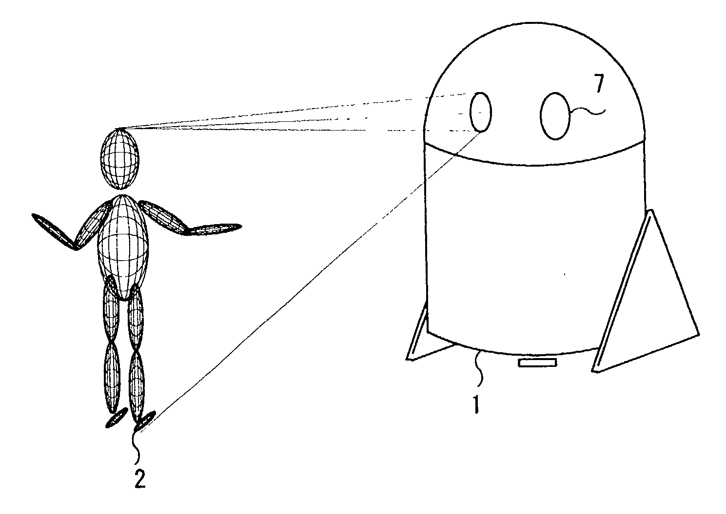
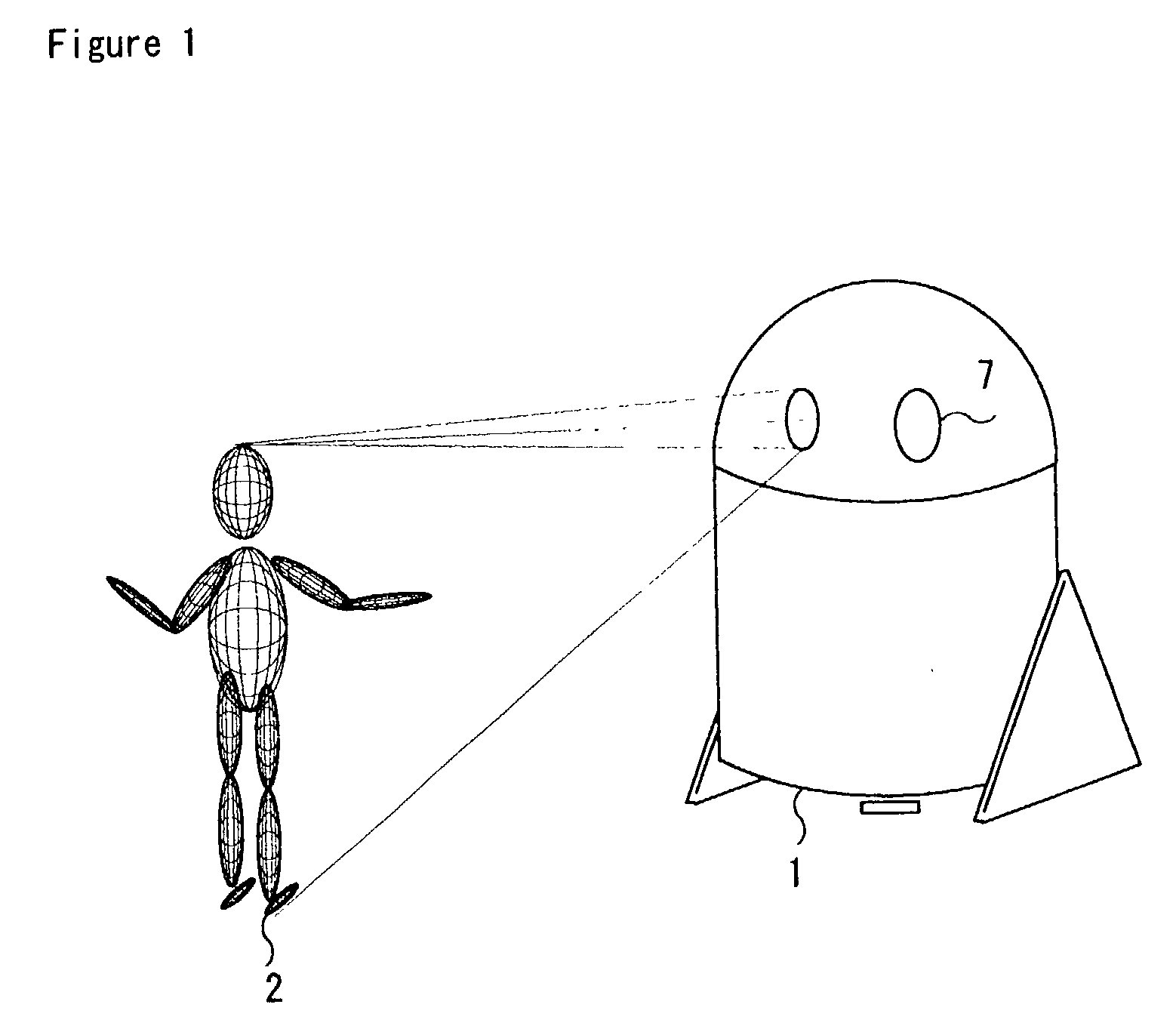
[0113] A preferred embodiment of the "3 dimensional image projector and holodeck" is illustrated in FIG. 1, FIG. 2, FIG. 3, FIG. 1_A3.

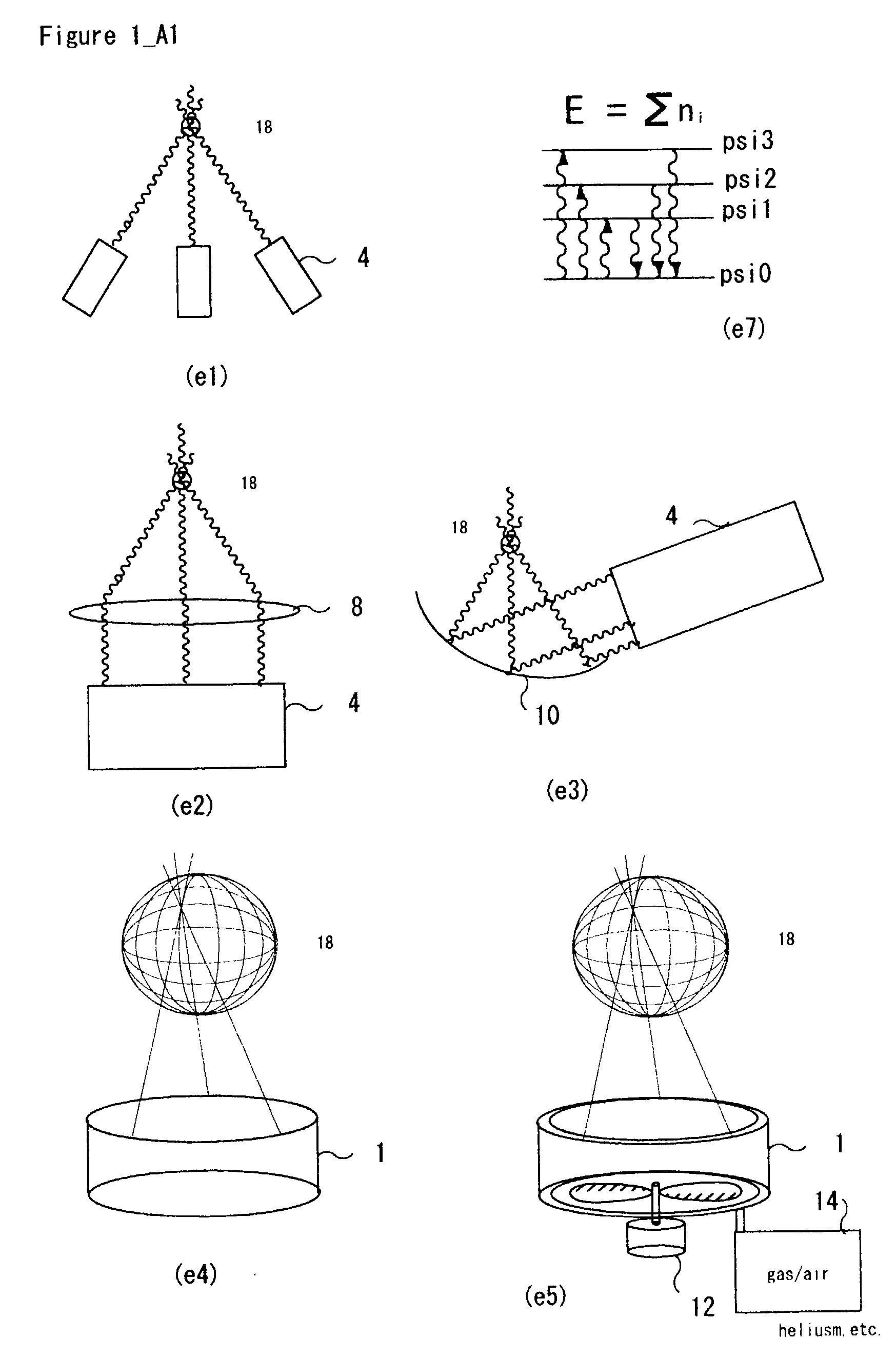
[0114] FIG. 1 shows the example diagram of 3 dimensional image projector means {1} displaying a 3D created image in the air. The 3 dimensional Image Generator of the type of FIG. 1_A3 (e1) has z axis control means {32} such as focusing beam means {8} such as microwave lens, and lens, magnet, and electric magnet together with beam direction changing means {52} such as x control means {30} and y control means {31} like polygon scanner, galvanometer with reflectors, acoustic crystal deflectors, electro-optic prisms / lenses, electric magnets.

[0115] The 3 dimensional Image Generator of the type of FIG. 1_A3 (e2) has multiple beam direction changing means {52} such as x, y, z axis control means {30,31,32} polygon scanner, galvanometer with reflectors, acoustic crystal deflectors, electro-optic prisms / lenses, electric magnets. Beam means {11} are emitted by t...


PUM


Abstract

By this invention, multi-users can view the 3 dimensional objects or images in real time (run time) without special glasses in the space or in the air or in space as the result of emitting light from points where beams merges in materials.

Description

FEDERALLY SPONSORED RESEARCH[0001] Not ApplicableSEQUENCE LISTING OR PROGRAM[0002] Not ApplicableBACKGROUND OF INVENTION[0003] 1. Field of Invention[0004] This invention relates to the image display devices, specifically to 3DTV, hologram, stereo display device that are used for displaying the 3 dimensional object or images and 3D scanners. 2. Description of Prior Art[0005] In the conventional way, it was difficult to display the 3 dimensional object or images in real time (run time) by viewed by the multiple users without special glasses in the space only by light. So devices such as TV are showing the converted 2 dimensional image from the 3 dimensional objects. Also, the virtual headsets are showing the two different images to each eye of users by screens to create the 3 dimensional images. Also, holograms are showing 3 dimensional image, but these images are difficult to be changed in real time (run time). Also, the method to project the 2 dimensional image to rotating plate to ...

Claims


Application Information

Patent Timeline
Patent Type & Authority Applications(United States)
IPC IPC(8): H04N13/00
CPCH04N13/0495H04N13/0493H04N13/395H04N13/393
Inventor YOSHINO, KAZUTORA
Owner LUMY
Why Eureka
Try Eureka