Articulating spinal implant

a spinal implant and articulating technology, applied in the field of spinal implants, can solve the problems of one or more, herniation, or other damage, intervertebral disc shrinkage, collapse, etc., and achieve the effect of reducing the number of vertebral discs, and improving the quality of li

Inactive Publication Date: 2004-03-11
WARSAW ORTHOPEDIC INC
View PDF36 Cites 166 Cited by
  • Summary
  • Abstract
  • Description
  • Claims
  • Application Information

AI Technical Summary

Problems solved by technology

Injury, disease or other degenerative disorders may cause one or more intervertebral discs to shrink, collapse, deteriorate or become displaced, herniated, or otherwise damaged.
This can lead to compression of adjacent nerve root(s) or the spinal cord causing chronic and often disabling pain, and in advanced circumstances, irreversible paralysis of upper and / or lower limbs.
This procedure disadvantageously requires the harvest of donor bone for the graft from other parts of the patient's body, typically requiring a separate surgical procedure and resultant increases in complications and expense.
Fusion of adjacent vertebra necessarily eliminates a portion of the spine's normal range of motion, thereby reducing the subject's spinal flexibility.
Additionally, long-term investigations after fusion of the vertebra have revealed deterioration in the next adjacent segments, ranging from increasing osteophyte formation, to collapse of the intervertebral disc, implicating progressive degeneration of the afflicted motion segment, resulting in hyper- and / or hypomobility of the segment.
It is believed that fusion results in nonphysiological bio-mechanical stress of the adjacent segment.
Changes in the PID may impair the nutrition of the intervertebral disc, which can lead to increased degeneration and pain in any plane of motion and / or compression of the spinal cord on spinal nerves.
Previously known devices of this type Generally have been found to suffer from inadequate attachment between the prosthesis and the vertebra.
Because such motion would disrupt bone ingrowth, jointed prostheses have generally been considered incompatible with attachment by bone ingrowth.
These mechanisms of attachment, however, may lack the degree and strength of fixation desired.
This has been found undesirable, as the extending flanges may interfere with or injure adjacent tissue; for example, it has been reported that flanges extending into immediately adjacent delicate esophageal areas may interfere with swallowing and speech, or cause perforation and potentially fatal infection.
An additional drawback to the use of screw and pin connections is the potential for such connectors to dislodge and cause injury.

Method used


Image

  • Articulating spinal implant
  • Articulating spinal implant
  • Articulating spinal implant

Examples


Embodiment Construction

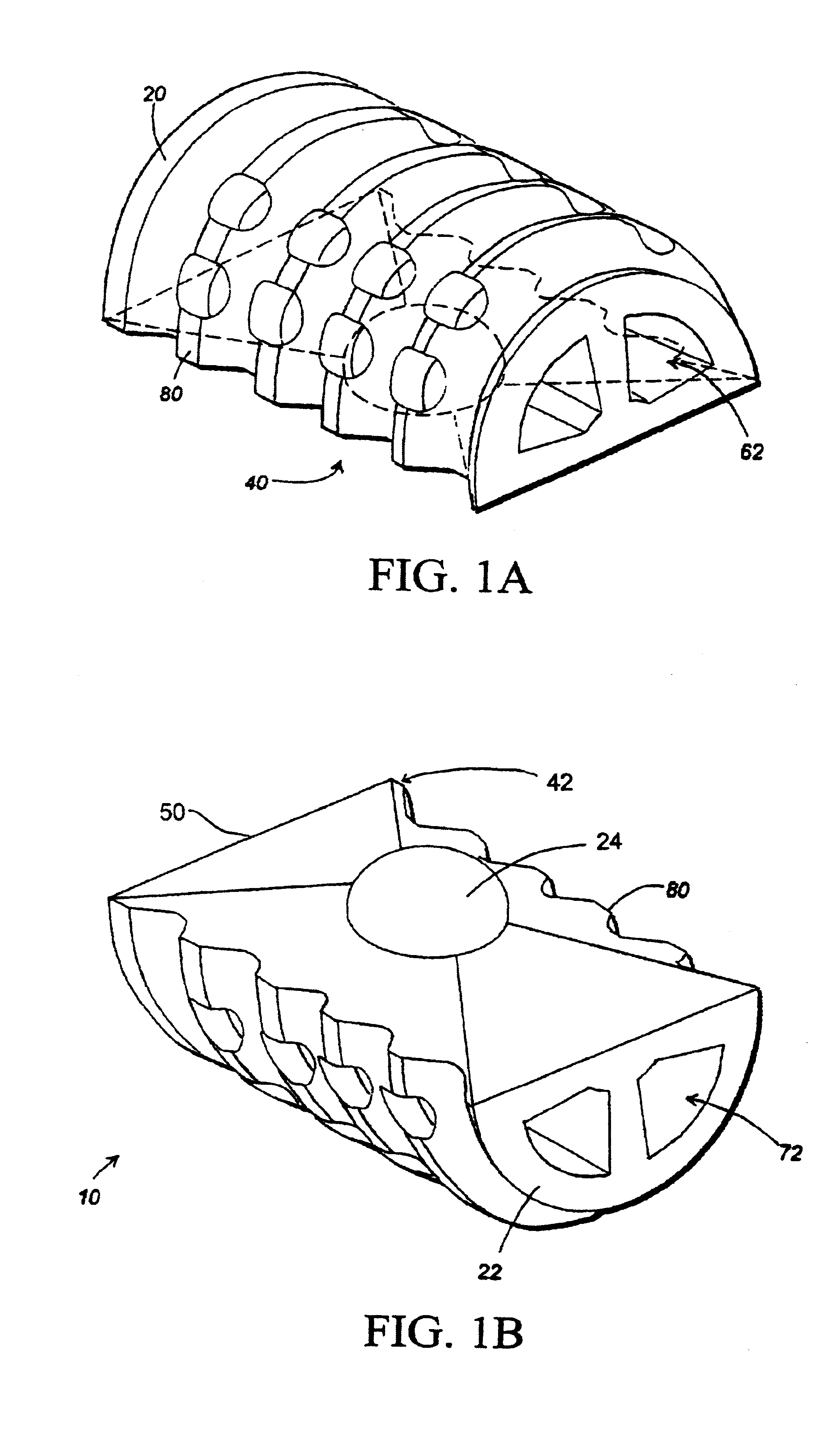
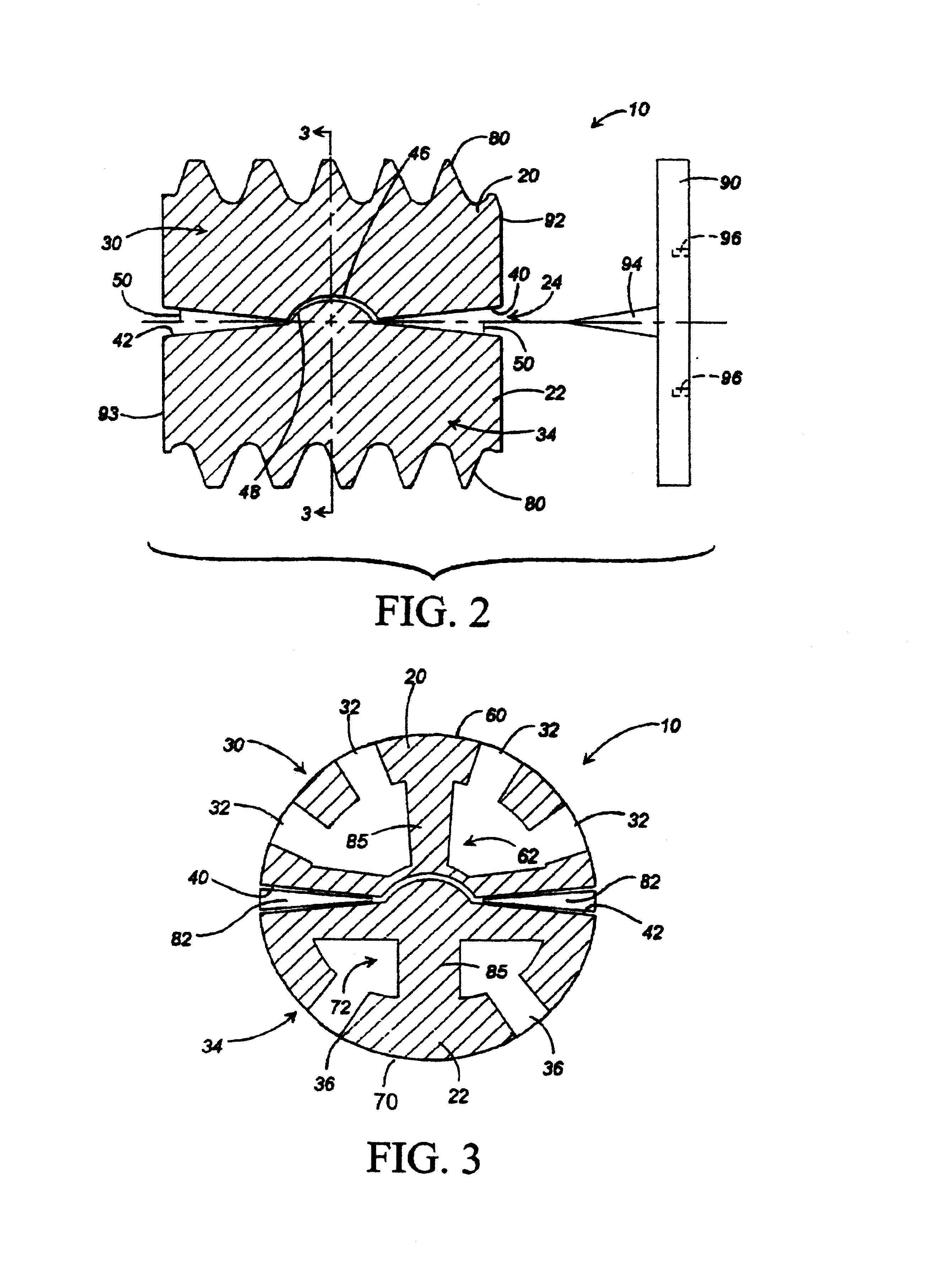
[0038] Referring now in detail to the figures, wherein like reference numbers represent like parts throughout, preferred forms of the present invention will now be described. As seen in FIGS. 1-3, one embodiment of the present invention comprises a spinal implant 10, generally comprising a first element 20 and a second element 22. The first element 20 is coupled to the second element 22 by an internal articulation means 24 for allowing relative pivotal movement between the first and second elements.

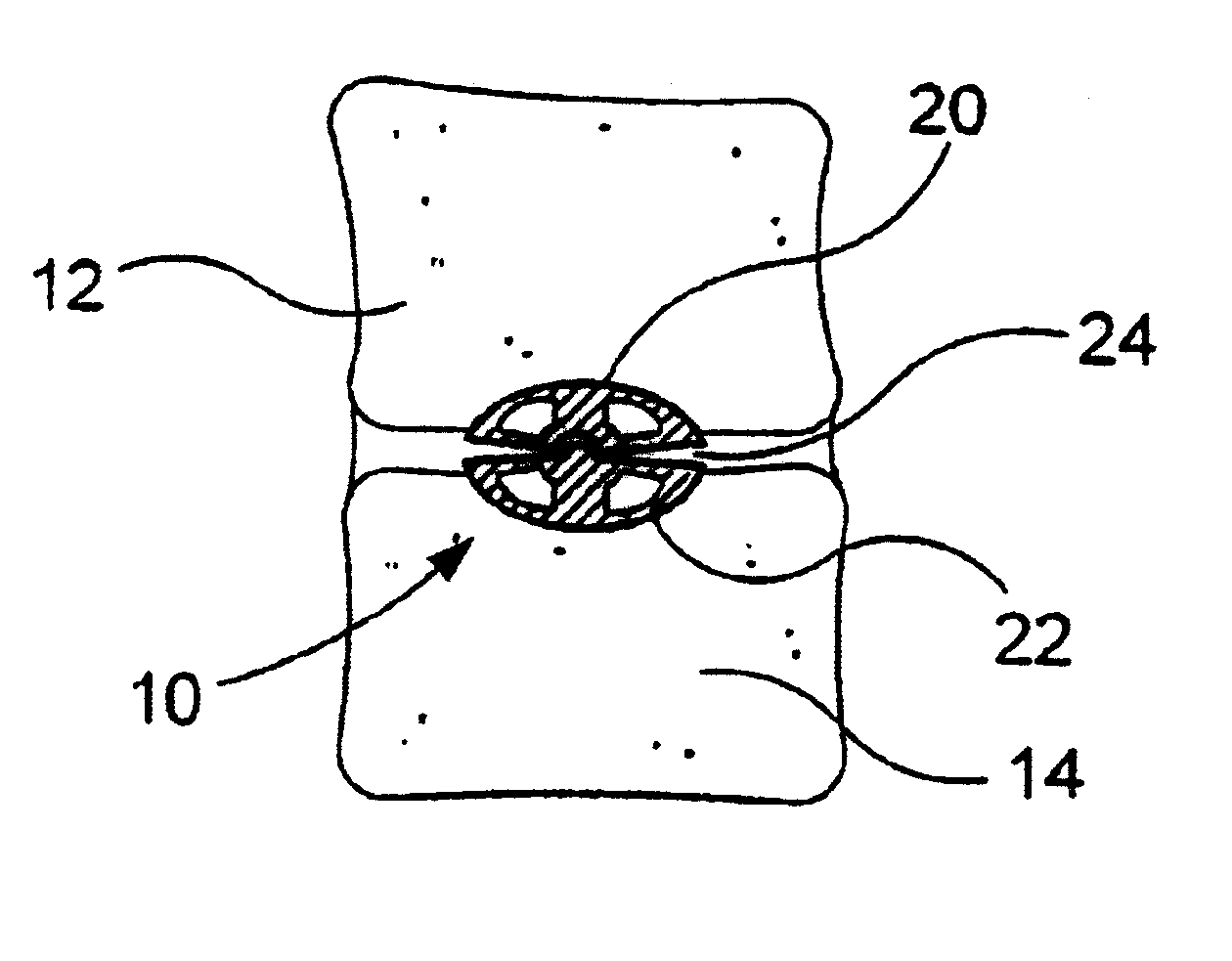
[0039] FIGS. 4A and 4B show the spinal implant 10 of the present invention installed in situ, between a first vertebra 12 and a second vertebra 14. The implant 10 is shown implanted into an anterior aspect of the vertebral body, between the fifth cervical and sixth cervical vertebra. The device and method of the present invention, however, are applicable to anterior, lateral, and posterior approaches to the vertebra.

[0040] As seen best in FIGS. 2-3, the first element 20 of the implant 10 ...


PUM

PropertyMeasurementUnit
bio-mechanical motionaaaaaaaaaa
lengthaaaaaaaaaa
widthaaaaaaaaaa

Abstract

An articulating spinal implant for interverteral disc replacement. The articulating spinal implant is formed from two elements, each engaging one of an adjacent pair of vertebra. An articulating means between the two elements resists compression and lateral movement between the vertebra, but allows the adjacent vertebra to articulate about an instantaneous axis of rotation.

Description

CROSS-REFERENCE TO A RELATED APPLICATION[0001] This application is a continuation-in-part of co-pending patent application Ser. No. 09 / 389,758, filed Sep. 2, 1999, which is a continuation-in-part of co-pending patent application Ser. No. 09 / 298,524, filed Apr. 23, 1999, which is a continuation-in-part of patent application Ser. No. 09 / 065,816, filed Apr. 23, 1998, now issued on Feb. 1, 2000 as U.S. Pat. No. 6,019,792.[0002] 1. Field of the Invention[0003] The invention relates Generally to spinal implants for use in intervertebral disc replacement; and more specifically relates to articulating implants that fuse to adjacent vertebra by bone ingrowth, thus restoring proper intervertebral spacing, and eliminating nerve root and / or spinal cord compression, while preserving spinal flexibility.[0004] 2. Description of Related Art[0005] The spinal column is formed from a number of vertebra, which in their normal state are separated from one another by cartilaginous intervertebral discs. T...

Claims


Application Information

Patent Timeline
Patent Type & Authority Applications(United States)
IPC IPC(8): A61B17/16A61F2/00A61F2/02A61F2/28A61F2/30A61F2/44A61F2/46
CPCA61B17/1604A61F2310/00634A61F2/30724A61F2/30744A61F2/30767A61F2/442A61F2/4425A61F2/446A61F2/4611A61F2002/2817A61F2002/2821A61F2002/2835A61F2002/30062A61F2002/30125A61F2002/30179A61F2002/3021A61F2002/30232A61F2002/30329A61F2002/30378A61F2002/30385A61F2002/30387A61F2002/3039A61F2002/30393A61F2002/30397A61F2002/30512A61F2002/30515A61F2002/30649A61F2002/30662A61F2002/30663A61F2002/30672A61F2002/30785A61F2002/30787A61F2002/3081A61F2002/30827A61F2002/3085A61F2002/30874A61F2002/30879A61F2002/30934A61F2002/30975A61F2002/443A61F2002/4475A61F2210/0004A61F2220/0025A61F2220/0033A61F2230/0008A61F2230/0058A61F2230/0067A61F2230/0069A61F2310/00017A61F2310/00023A61F2310/00029A61F2310/00059A61F2310/00239A61F2310/00293A61F2310/00401A61F2310/00407A61F2310/00413A61F2310/00449A61B17/1671A61F2002/30507A61F2002/30873A61F2002/30593
Inventor CAUTHEN, JOSEPH C.
Owner WARSAW ORTHOPEDIC INC
Why Eureka
Try Eureka