Expandable porous mesh bag device and methods of use for reduction, filling, fixation, and supporting of bone

a porous mesh bag and expansion technology, applied in the direction of osteosynthesis devices, endoscopic cutting instruments, prostheses, etc., can solve the problems of leakage, bag used by scribners may be ruptured during expansion, etc., and achieve the effect of less fear of puncture and safe skipping

Active Publication Date: 2007-06-05
SPINEOLOGY
View PDF81 Cites 409 Cited by
  • Summary
  • Abstract
  • Description
  • Claims
  • Application Information

AI Technical Summary

Benefits of technology

[0010]In cases in which the bone is to be compacted, the methods and devices of this invention employ a catheter tube attached to an inflatable porous fabric bag as described in U.S. Pat. Nos. 5,549,679 and 5,571,189 to Kuslich, the disclosures of which are incorporated herein by reference. Those bags may be inflated with less fear of puncture and leakage of the inflation medium than thin walled rubber balloons. They may also be used over a Scribner balloon to protect the balloon from breakage and eventually seepage.
[0011]The devices of U.S. Pat. Nos. 5,549,679 and 5,571,189 to Kuslich, additionally provide the surgeon with the advantage of safely skipping the first balloon inflation steps of Scribner and Scholten, by expanding the bag through introduction of fill material, such as a bone repair medium thereby correcting the bony defect and deformity and stabilizing it in one step of the procedure.

Problems solved by technology

Unfortunately, such leakage is known to occur in spite of these precautions.
Since such leakage may cause serious injury, including paralysis, an improved device and method is needed.
Unfortunately, the bag used by Scribner may be ruptured during expansion to compact cancellous bone due to sharp projections found within the cavity to be expanded.
Filling the cavity eventually formed could allow leakage of bone cement out of the bone against vessels or nerves which may cause undesirable complications.

Method used


Image

  • Expandable porous mesh bag device and methods of use for reduction, filling, fixation, and supporting of bone
  • Expandable porous mesh bag device and methods of use for reduction, filling, fixation, and supporting of bone
  • Expandable porous mesh bag device and methods of use for reduction, filling, fixation, and supporting of bone

Examples


Embodiment Construction

is hereafter described with specific reference being made to the drawings in which:

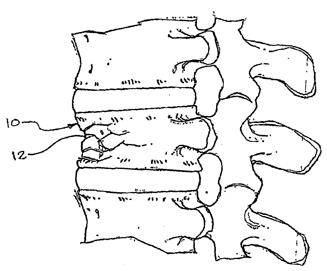
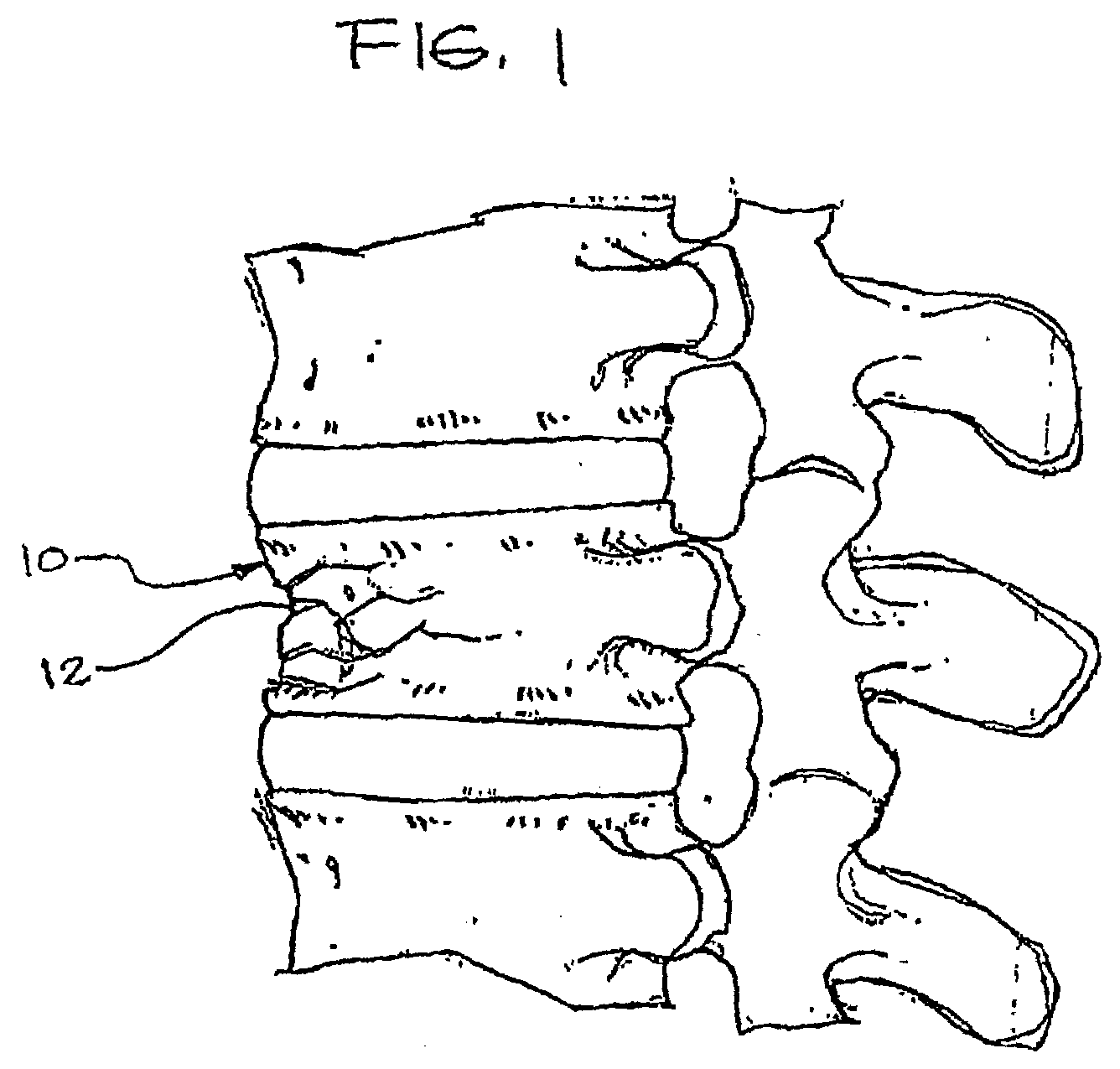
[0015]FIG. 1 is a side elevational view of a vertebra that is fractured and in need of repair;

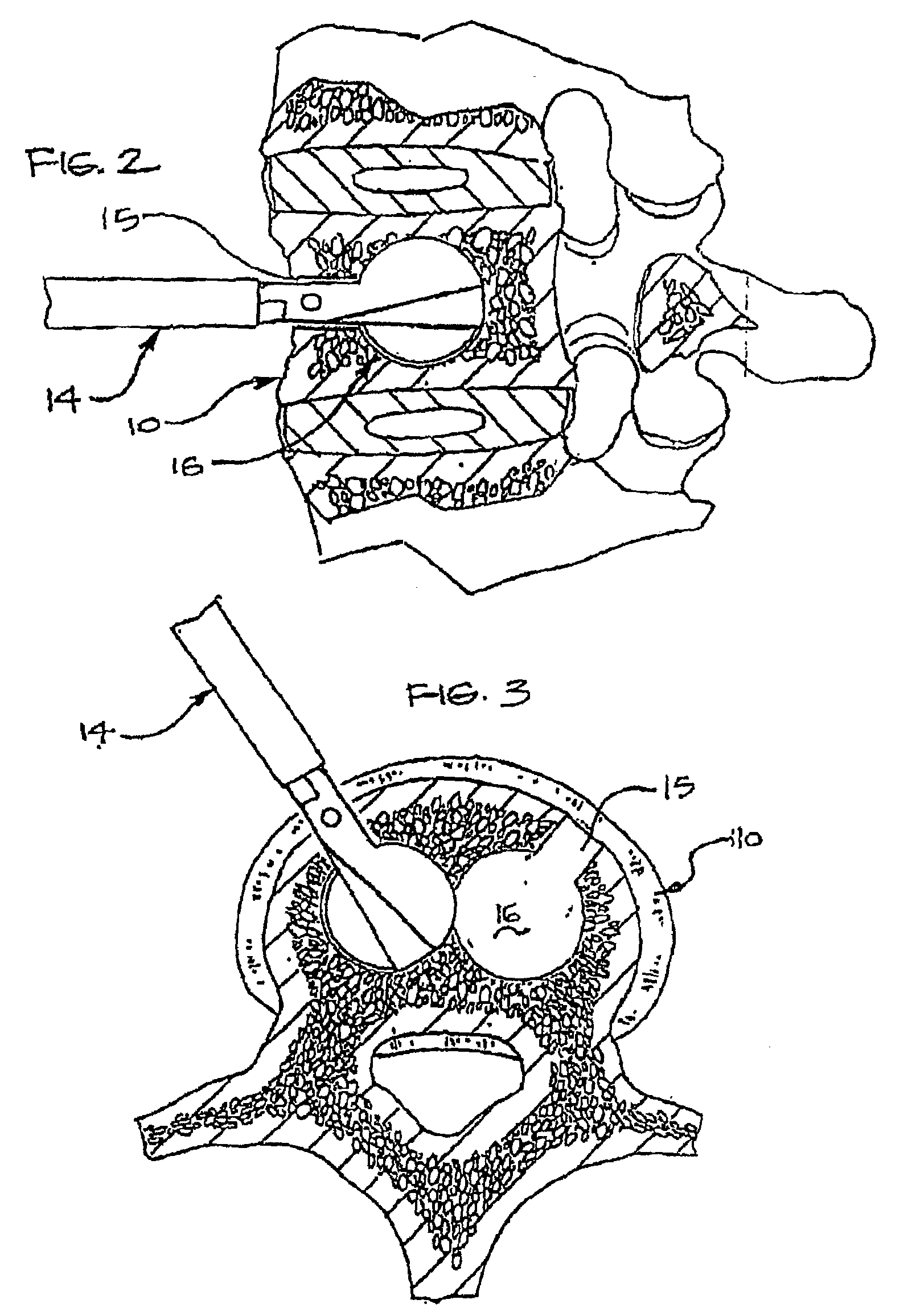
[0016]FIG. 2 is a side view of the vertebra of FIG. 1 being reamed out with a reaming tool from the anterior approach;

[0017]FIG. 3 is a top view of the vertebra of FIG. 1 showing the reamer forming a pair of cavities within the vertebra from the anterior approach;

[0018]FIG. 4 is a side elevational view of the vertebra of FIG. 2 showing placement of an expandable fabric bag of the invention;

[0019]FIG. 5 is a top elevational view of the vertebra of FIG. 3 showing a second of two expandable fabric bags of the invention being positioned;

[0020]FIG. 6 is a side view of a vertebra being reamed from a posterior approach;

[0021]FIG. 7 is a top view of the vertebra of FIG. 6 with a bag in place and a second cavity being reamed;

[0022]FIG. 8 is a side elevational view of the vertebra of FIG. 6 with an expandable fabric ba...


PUM

PropertyMeasurementUnit
diameteraaaaaaaaaa
diameteraaaaaaaaaa
diameteraaaaaaaaaa

Abstract

The invention provides a method of correcting numerous bone abnormalities including bone tumors and cysts, avascular necrosis of the femoral head, tibial plateau fractures and compression fractures of the spine. The abnormality may be corrected by first accessing and boring into the damaged tissue or bone and reaming out the damaged and / or diseased area using any of the presently accepted procedures or the damaged area may be prepared by expanding a bag within the damaged bone to compact cancellous bone. After removal and / or compaction of the damaged tissue the bone must be stabilized.

Description

CROSS-REFERENCE TO RELATED APPLICATIONS[0001]This application claims priority from U.S. patent application Ser. No. 09 / 909,667, filed Jul. 20, 2001 now abandoned, which claims priority to U.S. Provisional Application No. 60 / 219,853 filed Jul. 21, 2000, the entirety of which is incorporated herein by reference.BACKGROUND OF THE INVENTION[0002]This invention relates to methods and devices for correcting bone abnormalities and involves the use of a surgical mesh bag which is inserted into a prepared cavity in bone. The bag is inflated using bone replacement material to expand and fill the cavity.[0003]U.S. Pat. Nos. 5,549,679 and 5,571,189 to Kuslich, describe a device and method for stabilizing the spinal segment with an expandable, porous fabric implant for insertion into the interior of a reamed out disc which is packed with material to facilitate bony fusion. In the present invention, a similar bag is used to correct bone abnormalities including, but not limited to, bone tumors and...

Claims


Application Information

Patent Timeline
Patent Type & Authority Patents(United States)
IPC IPC(8): A61F2/44A61B17/00A61B17/32A61B17/34A61B17/68A61B17/70A61B17/88A61F2/00A61F2/28A61F2/30A61F2/34A61F2/46
CPCA61B17/68A61B17/7098A61B17/742A61B17/8855A61F2/441A61F2/4611A61B17/00234A61B17/1617A61B17/1668A61B17/1671A61B17/1675A61B17/32002A61B17/3472A61B17/8805A61B2017/00004A61B2017/00261A61B2017/00557A61F2/0095A61F2/34A61F2/44A61F2/4601A61F2/4607A61F2/461A61F2002/2817A61F2002/2828A61F2002/2832A61F2002/2835A61F2002/2892A61F2002/30034A61F2002/30069A61F2002/3025A61F2002/30271A61F2002/30448A61F2002/30451A61F2002/30581A61F2002/30718A61F2002/448A61F2002/4602A61F2002/4635A61F2002/4636A61F2220/005A61F2220/0058A61F2230/0071A61F2230/0082A61F2250/0031A61F2310/00293A61F2310/00353A61F2002/30032A61F2002/30242A61F2002/30261A61F2002/30593
Inventor KUSLICH, STEPHEN D.
Owner SPINEOLOGY
Why Eureka
Try Eureka