Service priorities in multi-cell network

a multi-cell network and priority technology, applied in the field of multi-cell network service priority, can solve the problems of not and achieving satisfactory distribution of different type of connections in the available technologies and cell types from the operator's point of view

Inactive Publication Date: 2004-03-18
INTELLECTUAL VENTURES I LLC
View PDF1 Cites 26 Cited by
  • Summary
  • Abstract
  • Description
  • Claims
  • Application Information

AI Technical Summary

Problems solved by technology

In current proposed systems the operator would have to rely on cell selection or handover algorithms provided by the vendor, which might not result in satisfactory distribution of different type of connections in the available technologies and cell types from the operators point of view.
Secondly, prior to the deployment of 3GPP networks it has not been common for an operator to

Method used


Image

  • Service priorities in multi-cell network
  • Service priorities in multi-cell network
  • Service priorities in multi-cell network

Examples


Embodiment Construction

[0035] The invention will now be described by way of reference to a particular, non-limiting, example. The example chosen is that of a network having both 2G and 3G services. The 2G services are GSM services, and the 3G services are 3GPP. In this example it is also assumed that the network supports enhanced 2G services, specifically EDGE. Furthermore for each of the services, it is assumed that the network provides both micro-cells and macro-cells.

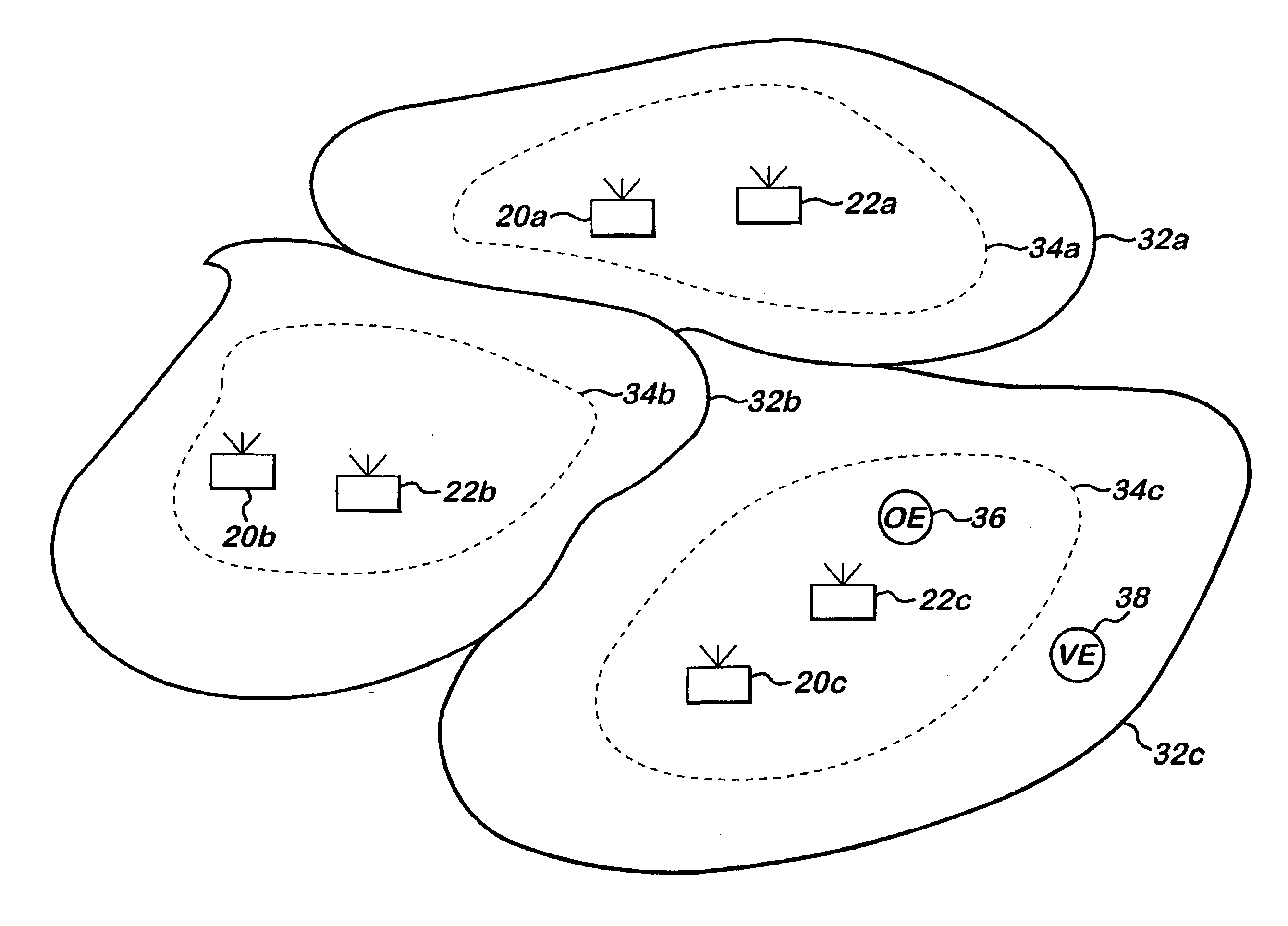
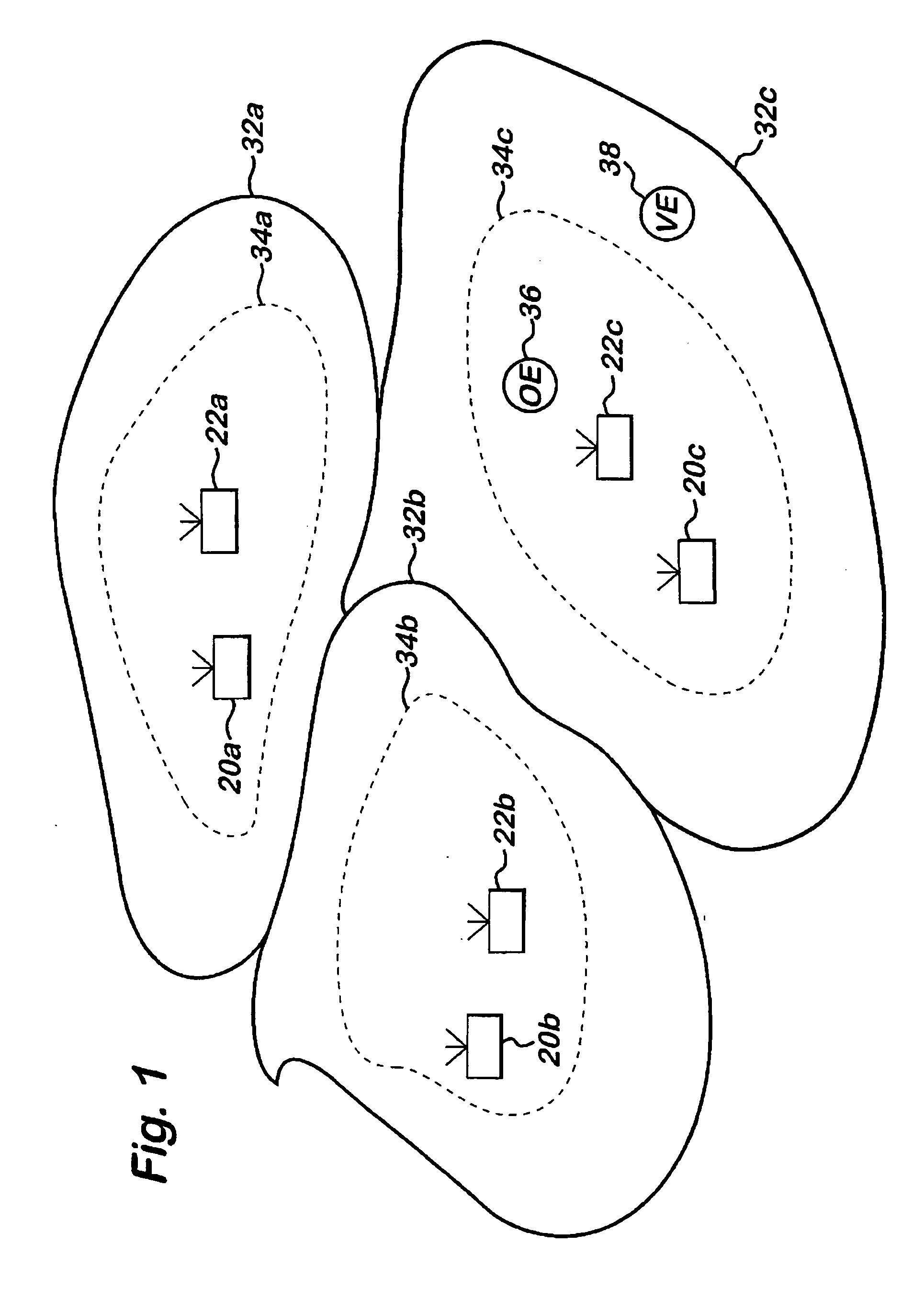
[0036] FIG. 1 illustrates cell coverage in such a network. FIG. 1 illustrates three GSM cells 32a to 32c. Each cell is supported by a GSM base station 22a to 22c. In addition, within each GSM cell there is provided 3GPP cell coverage, as illustrated by the dashed lines defining 3GPP cells 34a to 34c. In the example shown, it is assumed that 3GPP coverage is more restricted than GSM coverage. Each of the 3GPP cells is supported by a base station 20a to 20c. It should be noted that the 3GPP base stations are not necessarily co-located with t...


PUM


Abstract

There is provided a technique for determining cell allocation in a network supporting different communication standards.

Description

[0001] The present invention relates to wireless communication networks in which more than one communication standard is utilised, and particularly but not exclusively to wireless communication networks which support both 2.sup.nd and 3.sup.rd generation functionality.BACKGROUND TO THE INVENTION[0002] In the near future second-generation (2G) mobile networks will be complemented and partly replaced with third generation (3G) mobile networks. In many parts of the world this will mean a transition from a situation where the 2G standard is the only dominant mobile network technology to a situation where there are two dominant mobile network technologies: 2G and 3G. In Europe, for example, there will be a switch from GSM being the sole dominant standard to GSM and 3GPP (3.sup.rd Generation Partnership Project) both being dominant standards.[0003] Thus a network operator will in the future have often a mobile network containing GSM and 3GPP technology, where the 3GPP technology may be de...

Claims


Application Information

Patent Timeline
IPC IPC(8): H04L12/46H04L12/56H04W16/14H04W28/18H04W36/26H04W48/18
CPCH04W16/14H04W28/18H04W72/042H04W48/18H04W72/04H04W36/26H04W36/24H04W72/23
Inventor ARTAMO, ATTETIGERSTEDT, KARLHOLMA, HARRISCHWARZ, UWEHEIKKINEN, KAIWACKER, ACHIM
Owner INTELLECTUAL VENTURES I LLC
Why Eureka
Try Eureka