Crystal ball structure delivering multi-layer rotation and light effects

a technology of crystal ball and rotating surface, applied in the direction of instruments, display means, advertising, etc., can solve the problems of limiting the layout and degrading the dynamic

Inactive Publication Date: 2004-03-25
LIU JACK
View PDF8 Cites 12 Cited by
  • Summary
  • Abstract
  • Description
  • Claims
  • Application Information

AI Technical Summary

Benefits of technology

[0006] The main purpose of this invention is to provide a crystal ball structure delivering multi-layer rotation effect, comprising a crystal ball, a seat, ornaments, a rubber plug, model containers, a rotation mechanism, a driving mechanism, a light, and a music box, wherein the rotation mechanism comprises a fixed plate, first rotation plate, second rotation plate, a follower, and at least an idle gear between said first rotation plate and said second plate. The mechanic energy released from the fastened spiral power spring drives the driving mechanism, the follower, the first rotation plate, the idle gear, and the second rotation plate to rotate simultaneously. The first rotation plate and the second rotation plate can rotate in the same direction or in contrary directions at the same speed or at different speeds, depending on the number of idle gears between them. Thus the dynamic effect of the ornaments on the first rotation plate and the second rotation plate will be much richer.
[0007] Another purpose of this invention is to provide a crystal ball structure with light effect, i.e., a light is mounted on said first rotation plate or said fixed plate, and the light can rotate or stay still on the fixed plate when it illuminates, setting off the dynamic decorative effect of said scene.

Problems solved by technology

However, conventional dynamic scenic ornaments can only rotate in clockwise or counter clockwise, limiting the layouts of them and degrading the dynamic effect.

Method used


Image

  • Crystal ball structure delivering multi-layer rotation and light effects
  • Crystal ball structure delivering multi-layer rotation and light effects
  • Crystal ball structure delivering multi-layer rotation and light effects

Examples


first embodiment

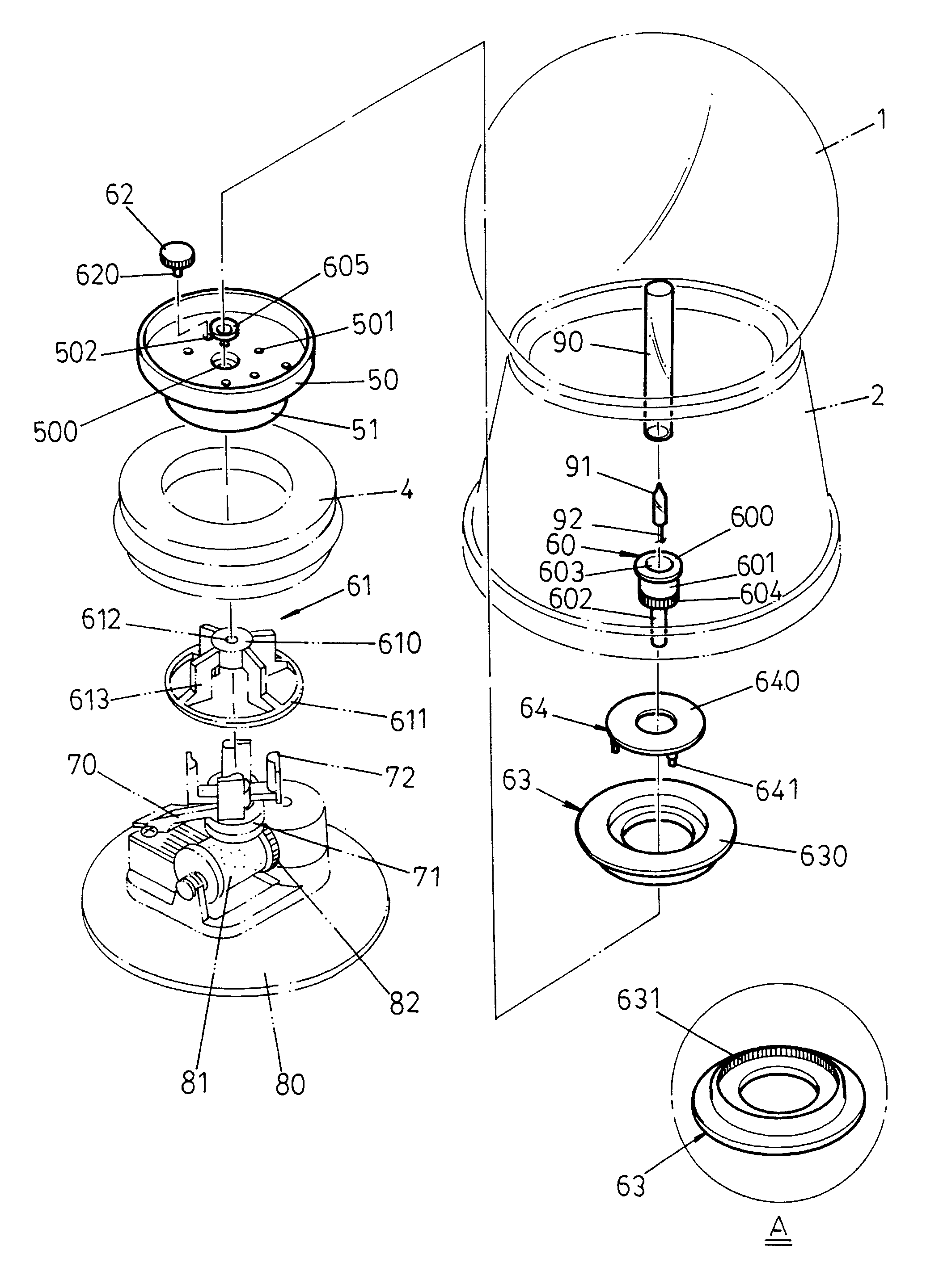
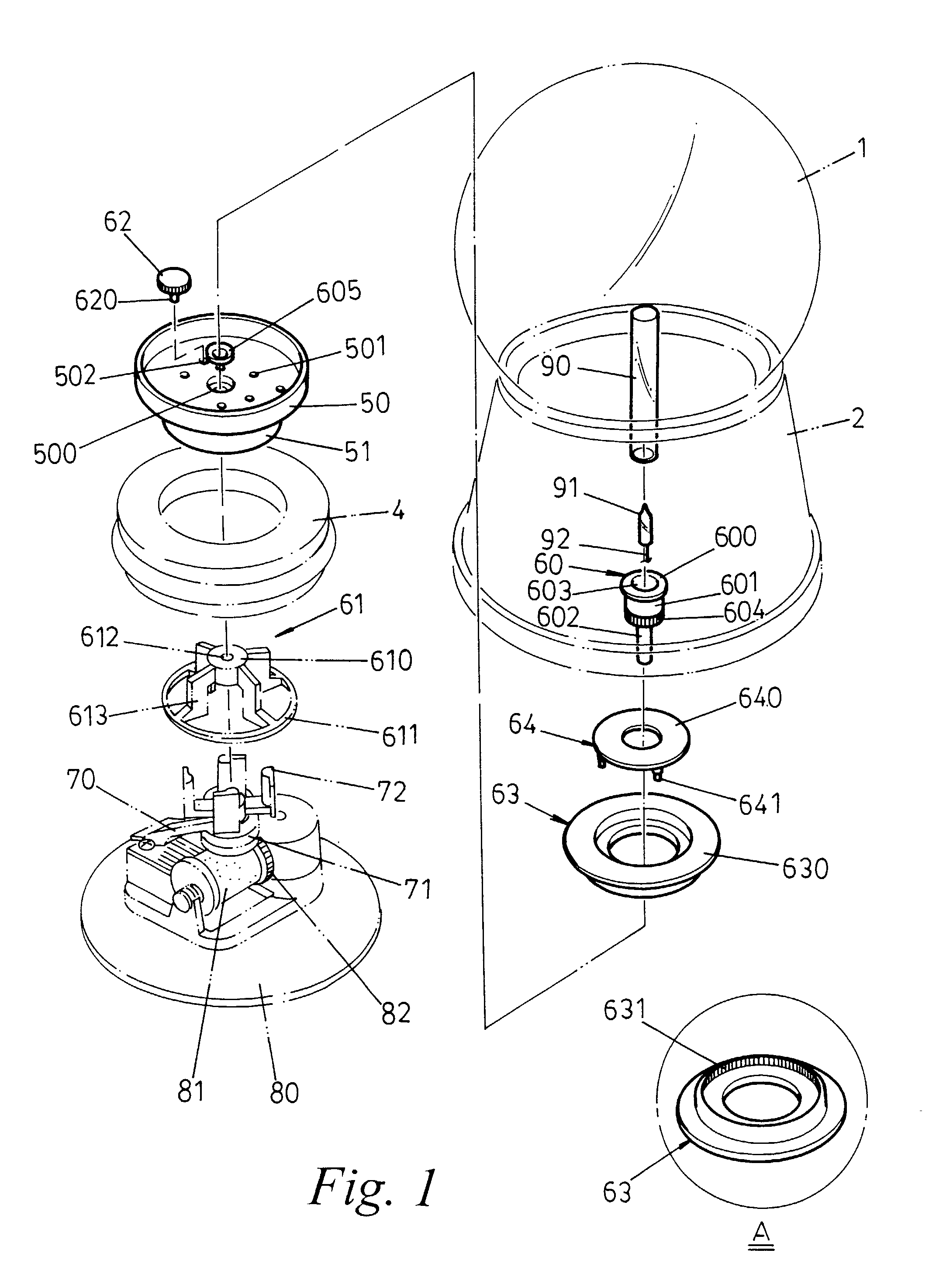
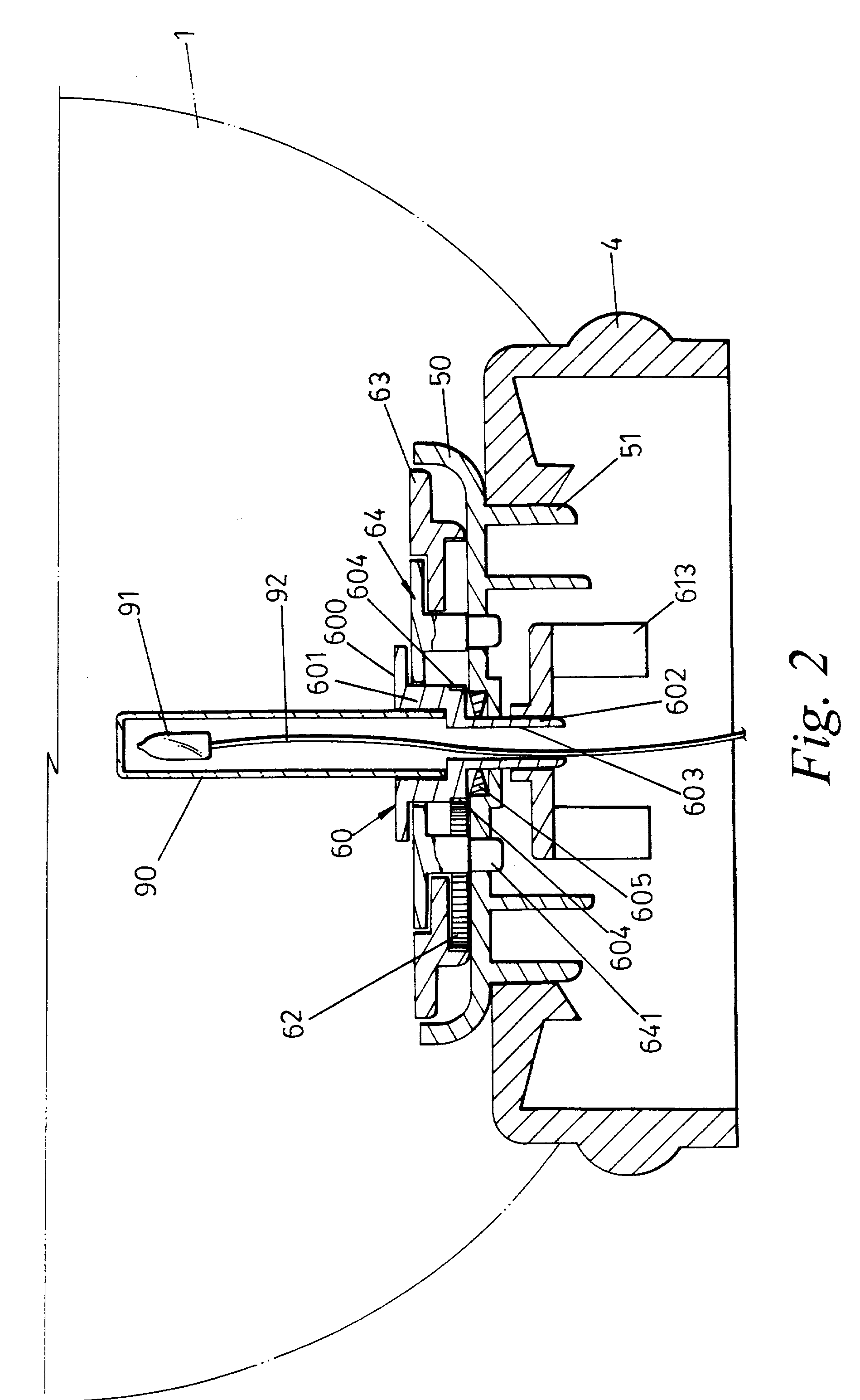
[0016] Please refer to FIG. 1 and FIG. 2 that are a 3D exploded view and a sectional view of the crystal ball according to this invention. Said embodiment comprises a crystal ball, a seat, ornaments, a rubber plug, model containers, a driving mechanism, a light, and a music box.

[0017] Wherein the music box also serves as the power source for the rotation of the ornaments. After the spiral power spring is fastened manually via the pivot under the seat and then released, it will drive the wheel 81 of the music box, and at the same time, drive the vertical driving gear 82.

[0018] The driving mechanism is mounted on a bracket 70 on top of the music box, and it is driven to rotate when the horizontal coronal gear 71 under the shaft and said driving gear 82 couple with each other. Thus the 4 driving arms 72 rotate along with the driving mechanism.

[0019] The follower 61 of the rotation mechanism comprises a central shaft 610 and a round ring 611, wherein the central shaft 610 has a hole 612...

second embodiment

[0037] In that way, the invention provides another driving pattern, i.e., the light and scenic model fixed on the fixed plate 64 stay still. However, the scenic model fixed on the second rotation plate 63 rotates around the fixed scenic model on said rotation plate 64. At the same time, the light fixed on the fixed plate 64 keeps illuminating, highlighting the scene.

[0038] In above first embodiment and the second embodiment, if the light is mounted on the first rotation plate 60 on the rotation mechanism, the light will rotate along with the first rotation plate 60; however, if the light is mounted on the fixed plate 64, the light will stay still. But in some cases, due to the limitation on scene design or the cost, the light has to be omitted. In the third embodiment of this invention, which is described hereunder, a crystal ball structure with multi-layer rotation effect but no light component is disclosed.

third embodiment

[0039] Please refer to FIG. 6 and FIG. 7 that are a 3D exploded view and a sectional view of crystal ball according to this invention. Wherein:

[0040] The model container comprise a round containing plate 50 and a hollow cylinder 51, wherein the containing plate 50 has a through hole 500, a fixing hole 501 and a position hole 502. The hollow cylinder 51 is agglutinate with a rubber plug 4;

[0041] The first rotation plate 60 on the rotation mechanism comprises a plate 600 containing a thematic model, a spur gear 604 under the plate 600, and a connecting shaft 602 under the plate 600, wherein the connecting shaft 602 is fitted with a shaft gland 605. The connecting shaft 602 runs through the through hole 500 of said containing plate 50 and is geared to the follower 61.

[0042] The follower 61 on the rotation mechanism comprises a central shaft 610 and a round ring 611, wherein the central shaft 610 has a hole 612, through which the central shaft 610 is coupled firmly with the connecting s...


PUM


Abstract

This invention is related to a crystal ball structure delivering multi-layer rotation and light effects, comprising a crystal ball, a seat, ornaments, a rubber plug, model containers, a rotation mechanism, a driving mechanism, a light, and a music box, wherein the rotation mechanism comprises a fixed plate, first rotation plate, second rotation plate, a follower, and at least an idle gear between said first rotation plate and said second plate. The mechanic energy released from the fastened spiral power spring drives the driving mechanism, the follower, the first rotation plate, the idle gear, and the second rotation plate to rotate. The light fixed on the first rotation plate or the fixed plate can rotate or stay still when it illuminates, setting off the dynamic effect of the ornaments.

Description

[0001] This invention is related to a crystal ball structure delivering multi-layer rotation and light effects, comprising a crystal ball, a seat, ornaments, a rubber plug, model containers, a rotation mechanism, a driving mechanism, a light, and a music box, wherein the rotation mechanism comprises a fixed plate, first rotation plate, second rotation plate, a follower, and at least an idle gear between said first rotation plate and said second plate. The mechanic energy released from the fastened spiral power spring drives the driving mechanism, the follower, the first rotation plate, the idle gear, and the second rotation plate to rotate. The light fixed on the first rotation plate or the fixed plate can rotate or stay still when it illuminates, setting off the dynamic decorative effect of the ornaments.BACKGROUND OF INVENTION[0002] A "dynamic scenic ornament" refers to a crystal ball enclosing decorative models of trees, houses, castles, cartoons, or their combinations with a dec...

Claims


Application Information

Patent Timeline
Patent Type & Authority Applications(United States)
IPC IPC(8): G09F19/02
CPCG09F19/02
Inventor LIU, JACK
Owner LIU JACK
Why Eureka
Try Eureka