Shoulder prosthesis having a removable conjoining component coupling a humeral component and humeral head and providing infinitely adjustable positioning of an articular surface of the humeral head

a shoulder and head technology, applied in the field of shoulder prostheses, can solve the problems of compromising fixation, affecting the healing effect of the shoulder, and not allowing surgeons to easily alter biomechanics, etc., and achieves the effect of reducing the risk of interfering with the resected bone and compromising fixation

Inactive Publication Date: 2004-04-01
DEPUY PROD INC
View PDF14 Cites 66 Cited by
  • Summary
  • Abstract
  • Description
  • Claims
  • Application Information

AI Technical Summary

Problems solved by technology

Even with respect to these two divergent manners of surgical strategy, a common problem in shoulder surgery is matching the humeral resection angle to the predetermined angle designed into the prosthesis.
This strategy does not allow the surgeon to easily alter biomechanics after the prosthesis has been trialed, much less implanted.
This system, however, has two primary weaknesses.
First, the use of modular blocks obviously forces the design to only allow angular adjustments in finite increments.
Second, the need to adjust the angle through modular blocks forces the surgeon to remove the stem, change out a component, and reset the stem.
This presents inconvenience, as well as risk for interfering with resected bone and compromising fixation.
Particularly, the locking mechanism, requires the turning of a locking screw that has its head facing lateral and inferior, for which there is no access once the stem has been cemented.
Lastly, the protrusion on the humeral stem even when the humeral head is not in place limits the surgeon's access to the glenoid in preparation for a glenoid replacement.

Method used


Image

  • Shoulder prosthesis having a removable conjoining component coupling a humeral component and humeral head and providing infinitely adjustable positioning of an articular surface of the humeral head
  • Shoulder prosthesis having a removable conjoining component coupling a humeral component and humeral head and providing infinitely adjustable positioning of an articular surface of the humeral head
  • Shoulder prosthesis having a removable conjoining component coupling a humeral component and humeral head and providing infinitely adjustable positioning of an articular surface of the humeral head

Examples


Embodiment Construction

)

[0044] While the invention is susceptible to various modifications and alternative forms, specific embodiments thereof have been shown by way of example in the drawings and will herein by described in detail. It should be understood, however, that there is no intent to limit the invention to the particular forms disclosed, but on the contrary, the intention is to cover all modifications, equivalents, and alternatives falling within the spirit and scope of the invention.

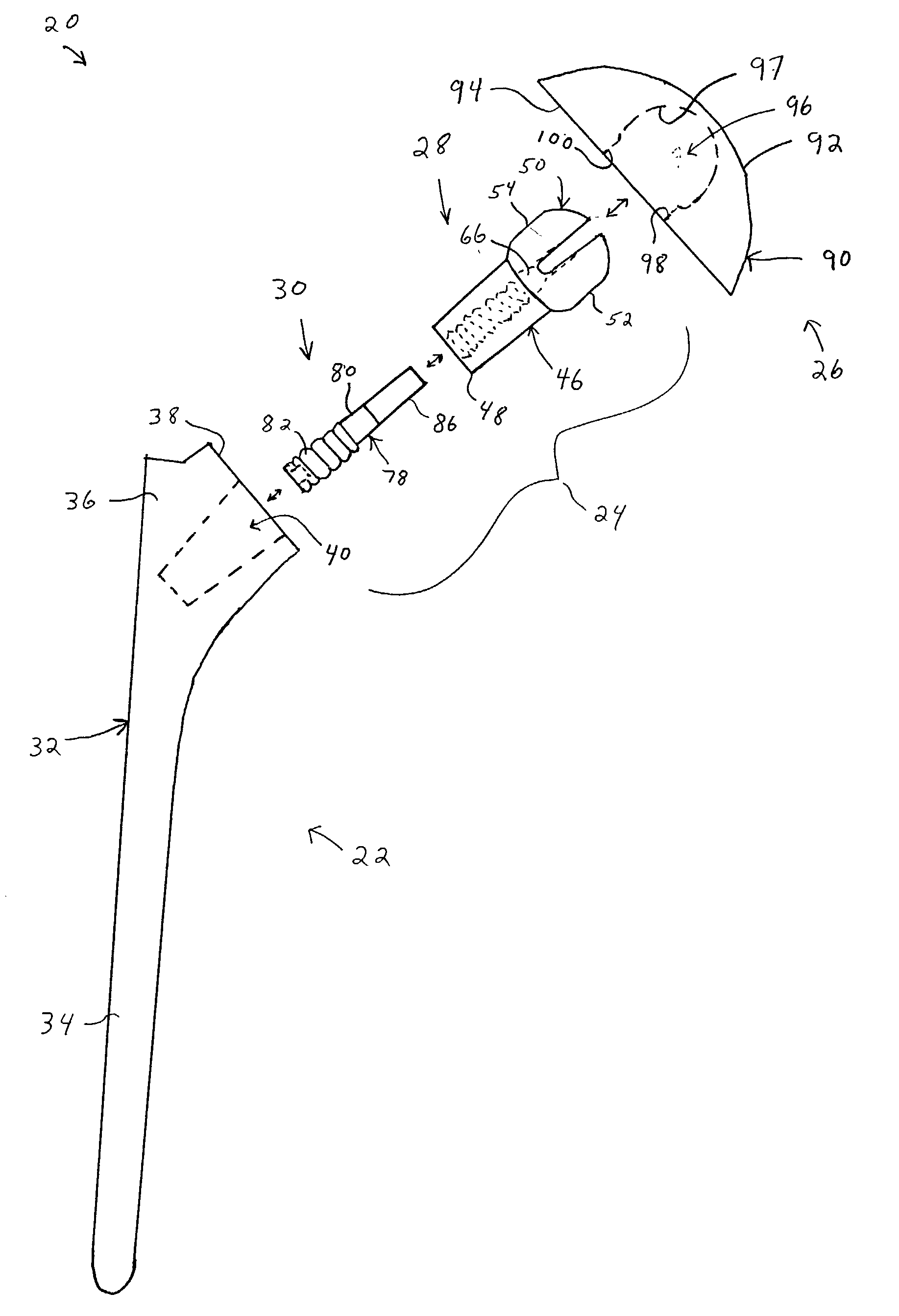
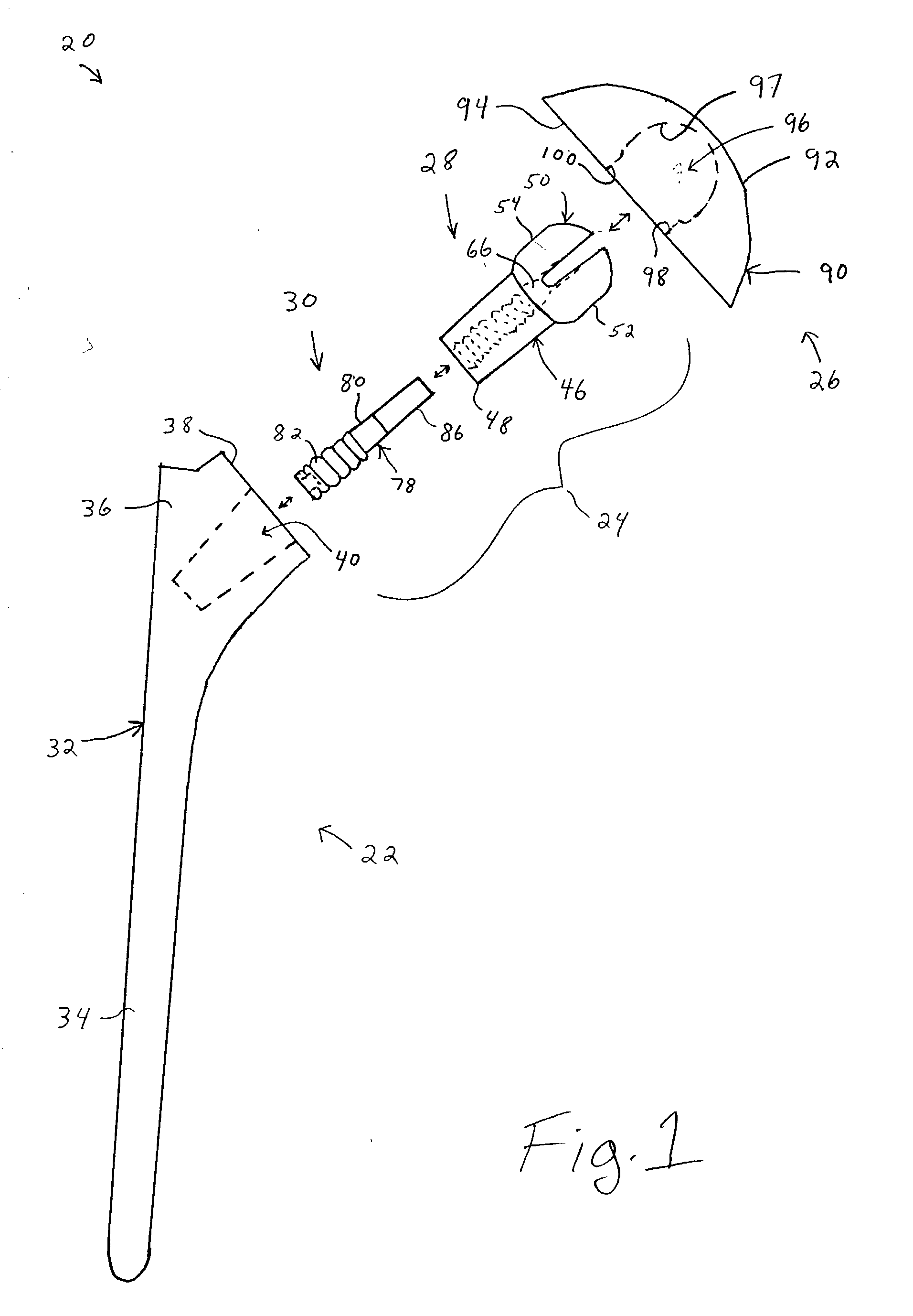
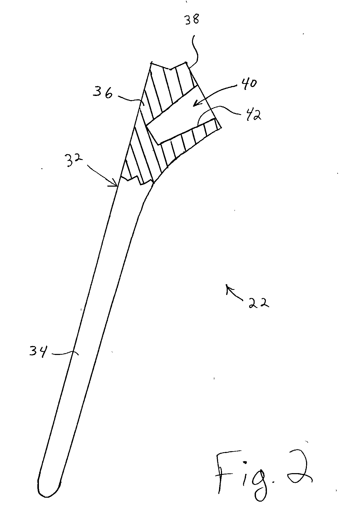
[0045] Referring now to FIG. 1 there is shown an exemplary embodiment of a shoulder prosthesis, generally designated 20. The shoulder prosthesis 20 includes a humeral component or stem 22, a conjoining and / or adjustment member or means 24, and a head 26. The head 26 is adapted, configured and / or operative to be received on the conjoining member 24 or vice versa (i.e. the conjoining member 24 is adapted, configured and / or operative to be received on the head 26) depending on the configurations of the head 26 and the c...


PUM


Abstract

A humeral prosthesis allows a surgeon to adjust humeral head position thereof in three-dimensional space with respect to a humeral component of the humeral prosthesis that has been either previously implanted into a humerus of a patient or not. The humeral prosthesis includes a conjoining component that is configured to releasably mate with the humeral component and to releasably mate with a humeral head. The conjoining component allows the humeral head to be selectively positionable from continuously infinite positions about two orthographic axes with respect to the conjoining component. The selected spatial position of the head is locked by a locking member of the conjoining component. The conjoining component allows the use of various sized heads, allow in vivo head trialing and/or exchange, and retrofit of heads for previously implanted shoulder prosthesis in need of revision.

Description

[0001] Cross-reference is made to co-pending U.S. patent application Ser. No. ______ filed on even date herewith entitled "Method and Apparatus for Replication of Angular Position of a Humeral Head of a Shoulder Prosthesis" by co-inventors Robert J. Ball and Jennifer M. Franklin, and commonly assigned.[0002] 1. Field of the Invention[0003] The present invention relates to prosthetic devices particularly shoulder prostheses and, more particularly, to a shoulder prosthesis and method of use for shoulder replacement.[0004] 2. Background Information[0005] The state of the prosthetic shoulder market has progressed such that a surgeon generally approaches shoulder replacement surgery in one of two strategic ways. One strategic manner is to perform the shoulder replacement surgery in accordance with a manufacturer's shoulder prosthesis or shoulder prosthesis product line. Particularly, a surgeon is provided with instrumentation and technique guidelines for the particular shoulder prosthesi...

Claims


Application Information

Patent Timeline
Patent Type & Authority Applications(United States)
IPC IPC(8): A61F2/00A61F2/02A61F2/30A61F2/40A61F2/46
CPCA61F2002/4018A61F2002/30884A61F2002/4037A61F2002/4044A61F2002/4062A61F2002/4631A61F2002/4638A61F2002/4668A61F2220/0025A61F2220/0033A61F2230/0017A61F2250/0006A61F2250/0097A61F2/40A61F2/4014A61F2/4059A61F2/4657A61F2/4684A61F2002/30143A61F2002/30329A61F2002/30332A61F2002/30378A61F2002/30484A61F2002/30507A61F2002/30538A61F2002/3054A61F2002/30598A61F2002/30604A61F2002/30616A61F2002/30617A61F2002/30774A61F2002/30795A61F2002/4029A61F2002/30594
Inventor BALL, ROBERT J.ONDRLA, JEFFREY M.
Owner DEPUY PROD INC
Why Eureka
Try Eureka