Optical film,polarizing film using the optical film, and method of improving visibility angle of polarizing film

a technology of optical film and polarizing film, applied in the field of optical film, can solve problems such as light leakage, and achieve the effect of improving the dependency on the view angl

Inactive Publication Date: 2004-04-08
NIPPON KAYAKU CO LTD +1
View PDF3 Cites 33 Cited by
  • Summary
  • Abstract
  • Description
  • Claims
  • Application Information

AI Technical Summary

Benefits of technology

[0004] In intensive studies for solving the above problems, the inventors have completed the present invention based on the novel founding that the light leakage generated by the tilting of the observation point from the front direction to a direction different from the respective absorption axis direction can be decreased, that the view angle dependency can be improved, and that even the wavelength dependency upon improving the view angle can be improved by means of an optical film prepared by laminating at least one first retardation film having a mean in-plane refractive index of n.sub.o and refractive index in the thickness direction of n.sub.e wherein n.sub.e-n.sub.o>0, and at least one second retardation film having a refractive index of n.sub.x in the direction exhibiting the maximum in-plane refractive index, refractive index of n.sub.y in the direction perpendicular to the direction mentioned just before and refractive index of n.sub.z in the thickness direction wherein n.sub.x.gtoreq.n.sub.y>n.sub.z, and by means of a polarizing film prepared by laminating the optical film and a polarizing element, provided that the above polarizing film is arranged with another polarizing element or with a polarizing film having said another polarizing element sandwiched between two protective films so that the respective absorption axis directions will be perpendicular to each other.

Problems solved by technology

However, when two sheets of such polarizing elements or polarizing films are disposed so that the respective absorption axis will be perpendicular to each other, there occurs a problem of the light leakage, so-called the view angle dependency of the polarizing element or polarizing film as the observation point is tilted from the front direction to a direction different from the direction of the respective axis because a polarized light passed through an incident side polarizing element or polarizing film can not be sufficiently absorbed by an emergent side polarizing film.

Method used


Image

  • Optical film,polarizing film using the optical film, and method of improving visibility angle of polarizing film
  • Optical film,polarizing film using the optical film, and method of improving visibility angle of polarizing film
  • Optical film,polarizing film using the optical film, and method of improving visibility angle of polarizing film

Examples


example 1

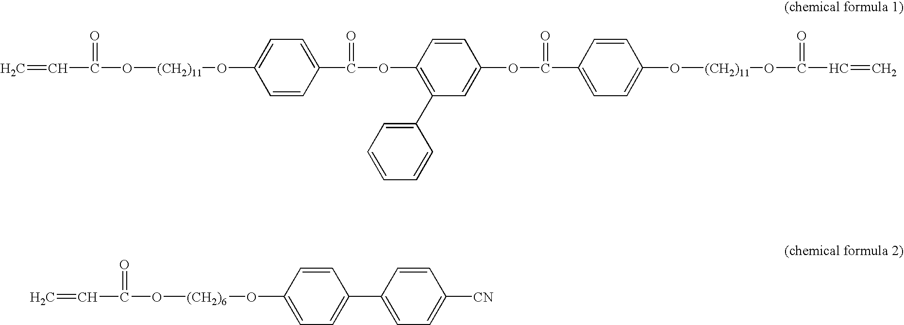
[0110] A solution with a solid fraction concentration of 20% was prepared by dissolving a mixture of 23.5 parts by weight and 70.5 parts by weight of UV curable liquid crystalline compounds described in WO 97 / 44703 as shown in the chemical formulae (1) and (2), respectively, and 6 parts by weight of a photopolymerization initiator Irga-cure 907 (Ciba Specialty Chemicals Co.) in a mixed solvent of 300 parts by weight of toluene and 100 parts by weight of cyclohexanone. 1

[0111] This solution was applied on the polarizing element side of an iodide based polarizing film made by Polatechno Co. (the content of borate in polyvinyl alcohol having a degree of polymerization of 1700 and a thickness of about 20 .mu.m after stretching is 15%; the polyvinyl alcohol film is bonded to one face of a triacetyl cellulose film as a protective film having surface layers treated with an alkali using a polyvinyl alcohol adhesive) using a wire bar. A polarizing film having a first retardation film was obt...

example 2

[0112] The polarizing film of the invention was obtained by the same method as in Example 1, except that one sheet of the second retardation film, or a polycarbonate film, was laminated on the surface of the first retardation film of the polarizing film (.DELTA.n.sub.p.multidot.d.sub.p=-39 nm) used in Example 1 with a PSA so that the n.sub.x direction aligns with the direction of the absorption axis of the polarizing element. The second retardation film had a refractive index n.sub.x of 1.5864 in the direction showing the maximum in-plane refractive index, a refractive index n.sub.y of 1.5844 in the direction perpendicular to the direction described just before, a refractive index n.sub.z of 1.5841 in the thickness direction, a thickness d of 70 .mu.m, and the value of (n.sub.x-n.sub.y).multidot.d of 140 nm at 550 nm. This polarizing film was bonded to the iodide based polarizing film (made by Polatechno Co.) used in Example 1 with a PSA so that the absorption axes of the polarizing...

example 3

[0113] The first retardation film (.DELTA.n.sub.p.multidot.d.sub.p=65 nm) prepared by the same procedure as in Example 1 was bonded to the third retardation film, or a triacetyl cellulose film having a sticky layer on one surface and surface layers thereof are treated with an alkali, and the first retardation film was peeled off from the polarizing element. The triacetyl cellulose film had a refractive index n.sub.x of 1.49522 in the direction showing the maximum in-plane refractive index, a refractive index n.sub.y of 1.49517 in the direction perpendicular to the direction described just before, a refractive index n.sub.z (n.sub.e) of 1.49461 in the thickness direction, a thickness d.sub.n of 80 .mu.m, a mean in-plane refractive index n.sub.o of 1.49520, and .vertline..DELTA.n.sub.n.multido-t.dn.sub.n.vertline. of 49 nm with a relation of n.sub.e-n.sub.o=.DELTA.nn-. Then, the second retardation film, or a polycarbonate film having (n.sub.x-n.sub.y).multidot.d of 140 nm at 550 nm us...


PUM

PropertyMeasurementUnit
thicknessaaaaaaaaaa
thicknessaaaaaaaaaa
thicknessaaaaaaaaaa

Abstract

The invention provides an optical film prepared by laminating at least one of a first retardation film (2), having a mean in-plane refractive index of no and refractive index in the thickness direction of ne wherein ne-no>0, and at least one of a second retardation film (3) having an in-plane refractive index of nx in the direction showing the maximum refractive index, refractive index of ny in the direction perpendicular to the direction described just before, and refractive index in the thickness direction of nz wherein nx >ny>nz. The light leakage occurred as the observation point is tilted from the front direction to a direction different from the direction of each absorption axis can be reduced when a plolarizing film is arranged so that the absorption axes will be perpendicular to each other.

Description

[0001] The present invention relates to a polarizing film and retardation film to be used for a liquid crystal display device.[0002] A polarizing film that is an essential optical member for a liquid crystal display device is obtained by disposing, using an adhesive, a polarizing element between protective films such as a triacetyl cellulose film whose surface layer having been treated with an alkaline. The polarizing element is obtained, for example, by uniaxially orienting a polyvinyl alcohol film impregnated with a water soluble dichromatic dye or a dichromatic pigment such as polyiodide ions in a warm aqueous boric acid solution, by forming a polyene structure by means of a dehydration reaction after uniaxially orienting a polyvinyl alcohol film.[0003] However, when two sheets of such polarizing elements or polarizing films are disposed so that the respective absorption axis will be perpendicular to each other, there occurs a problem of the light leakage, so-called the view angl...

Claims


Application Information

Patent Timeline
Patent Type & Authority Applications(United States)
IPC IPC(8): G02B5/30G02F1/13363
CPCG02F1/133634G02B5/3083G02F1/13363
Inventor TANAKA, KOUICHI
Owner NIPPON KAYAKU CO LTD
Why Eureka
Try Eureka