Filter for segmenting power lines for communications

a technology of power line communication and filter, applied in the field of power line communication, can solve the problems of interrupting a power line circuit, inacceptable customer service, and signal appearance to modem receivers as background nois

Active Publication Date: 2004-05-06
ERICSSON INC
View PDF6 Cites 8 Cited by
  • Summary
  • Abstract
  • Description
  • Claims
  • Application Information

AI Technical Summary

Problems solved by technology

Over distances of hundreds of meters, there can be significant induction of signal from one set of lines to another, and these induced sig

Method used


Image

  • Filter for segmenting power lines for communications
  • Filter for segmenting power lines for communications
  • Filter for segmenting power lines for communications

Examples


Embodiment Construction

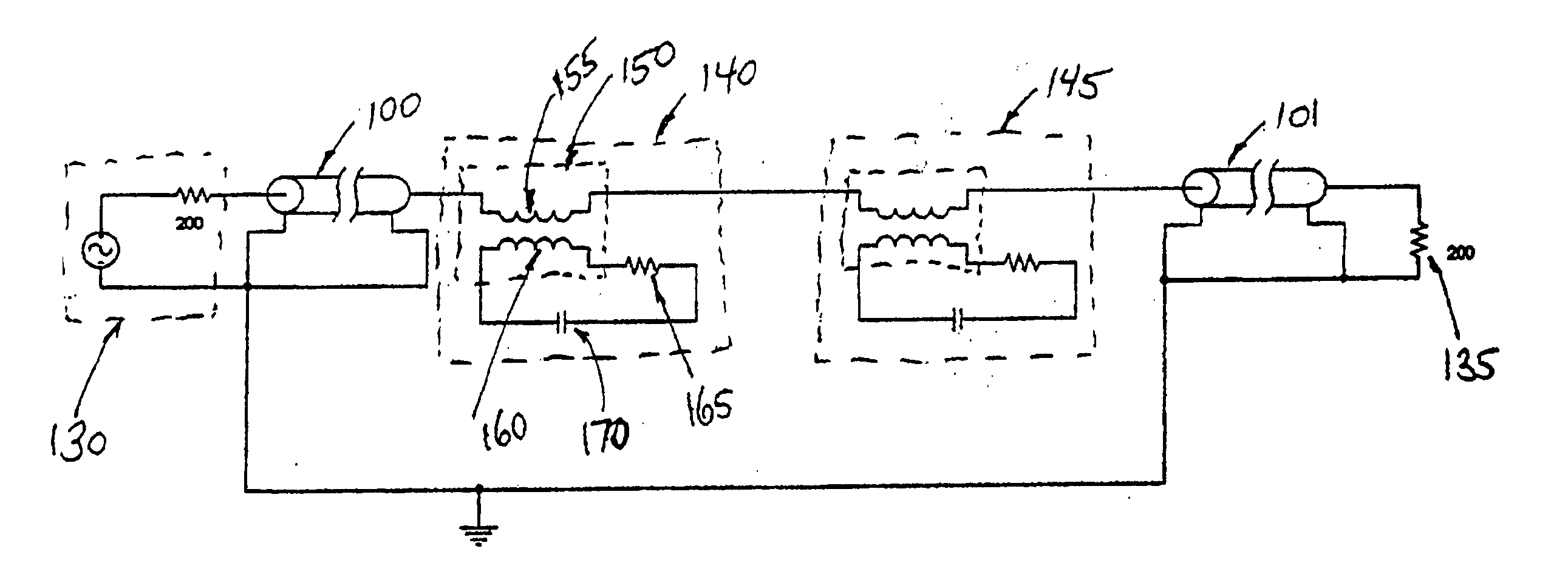
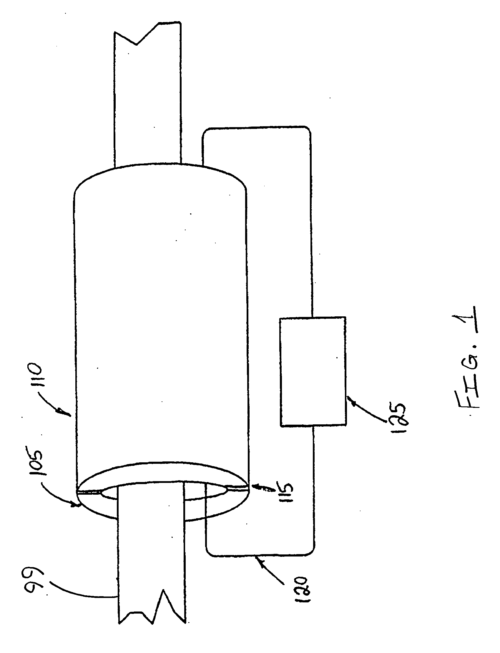
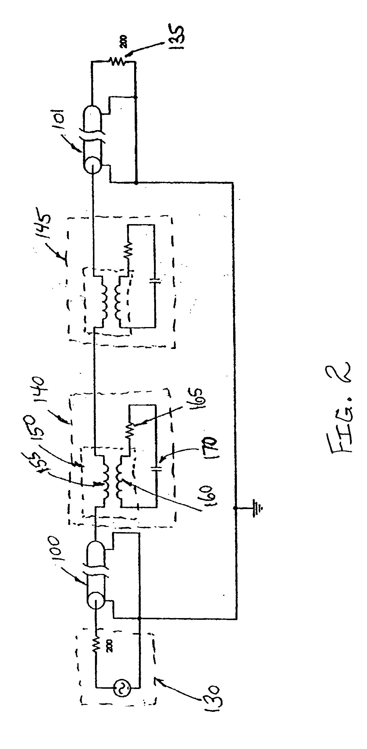
[0011] A signal filter in accordance with the present invention achieves segmentation of lines over specific frequency bands, without interrupting service. A series-connected filter, in the form of a filter, i.e. a clamp-on filter, is clamped onto an energized power line. The clamp-on filter includes a split magnetic core and a secondary coil, across which a capacitor is connected so as to create a parallel resonant circuit. The impedance of the parallel resonant circuit is coupled into the power line circuit, thus introducing a series impedance having a magnitude that is substantial over a particular frequency band. When the particular frequency band includes the spurious signal frequency, the filter reduces the magnitude of spurious current flowing in the power line.

[0012] For spread spectrum communications, the width of a communications frequency band is typically wider than a resonance band achieved by a single LC circuit. A wider band-blocking filter can be achieved by using tw...


PUM


Abstract

There is provided a method for blocking a portion of energy of a signal in a power line. The method includes equipping a high frequency magnetic core with a coil, connecting a capacitor across terminals of the coil to create a resonant circuit that resonates at a frequency of the signal, and placing the magnetic core around the power line, at a location where the blocking is desired.

Description

[0001] The present application is claiming priority of U.S. Provisional Patent Application Serial No. 60 / 419,174, filed on Oct. 17, 2002, the content of which is herein incorporated by reference.[0002] 1. Field of the Invention[0003] The present invention relates to power line communications, and more particularly, to a technique for blocking a portion of energy of a signal, e.g., a spurious signal in a power line.[0004] 2. Description of the Related Art[0005] Power line communications systems may send data signals over multiple sets of proximate lines, such as medium voltage and low voltage lines strung on the same utility poles or multiple sets of lines of the same voltage class on the same poles. Over distances of hundreds of meters, there can be significant induction of signal from one set of lines to another, and these induced signals can appear to modem receivers as background noise.[0006] To some extent, the induced signal strength is a function of the cumulative distance tha...

Claims


Application Information

Patent Timeline
IPC IPC(8): H01F17/06H01F38/14H01F38/20H01P1/32H03H1/00H03H5/00H03H7/01H03H7/09H03H7/38H04B3/36H04B3/38H04B3/54H04B3/56H04M11/04
CPCH01F17/06H04B2203/5491H03H7/0115H03H7/0138H03H7/38H03H2001/0092H03H2007/013H04B3/38H04B3/54H04B3/542H04B3/56H04B2203/5408H04B2203/5425H04B2203/5479H04B2203/5483H01F2038/143H01F38/02H01P1/32H04M11/04
Inventor CERN, YEHUDA
Owner ERICSSON INC
Why Eureka
Try Eureka