Leveredged wind turbine w/ multiple generators

a technology of generators and wind turbines, which is applied in the direction of machines/engines, renewable energy generation, greenhouse gas reduction, etc., can solve the problems of not being able to turn multiple generators, and no applicant can find that ever disclosed

Inactive Publication Date: 2004-05-06
PAGE JOHN S JR
View PDF9 Cites 65 Cited by
  • Summary
  • Abstract
  • Description
  • Claims
  • Application Information

AI Technical Summary

Benefits of technology

0016] Turning multiple generators would not be possible if applicant had not solved the problem of wind striking both sides of a vertical drive turbine and its wind blocking means. Applicant solved this problem with a Wind blocking means that has two unique modes of operation or positions. One is when wind strikes it from behind it rotates down 90 degrees against stops to a wind blocking status, thereby generating thrust to turn the turbine. Then when the turbine revolves around so that the Wind blocking means moves around so that it is traveling side ways through the wind and then straight into the wind, it rotates up 90 degrees to a horizontal position. In that position, it has a low profile so the wind has little to push on to cause drag. It has a unique t

Problems solved by technology

There are many wind devices in the archives of expired patents designed to do work of some kind of work but none that applicant can find that ever disclosed the two unique features of applicant's invent

Method used


Image

  • Leveredged wind turbine w/ multiple generators
  • Leveredged wind turbine w/ multiple generators
  • Leveredged wind turbine w/ multiple generators

Examples


Embodiment Construction

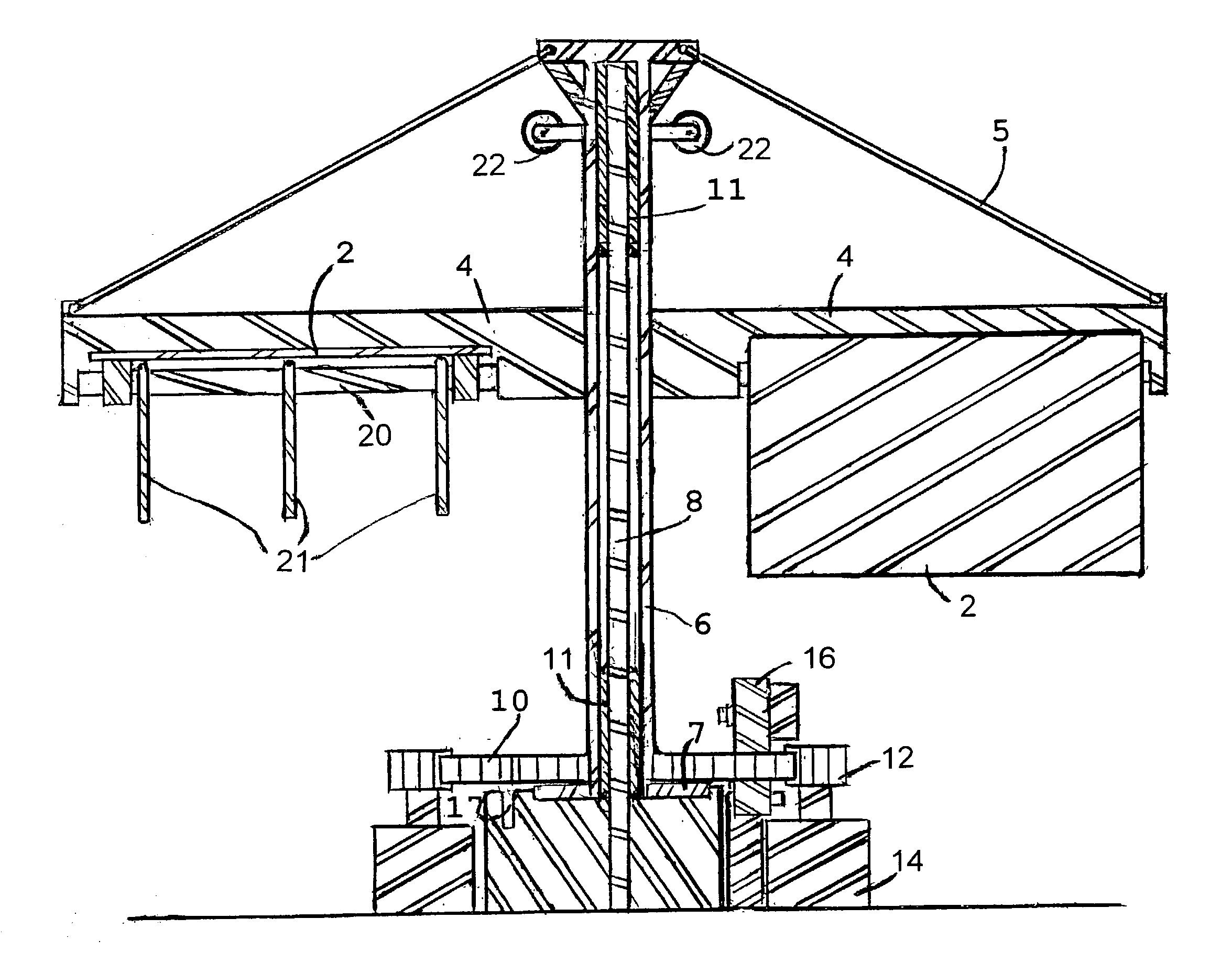
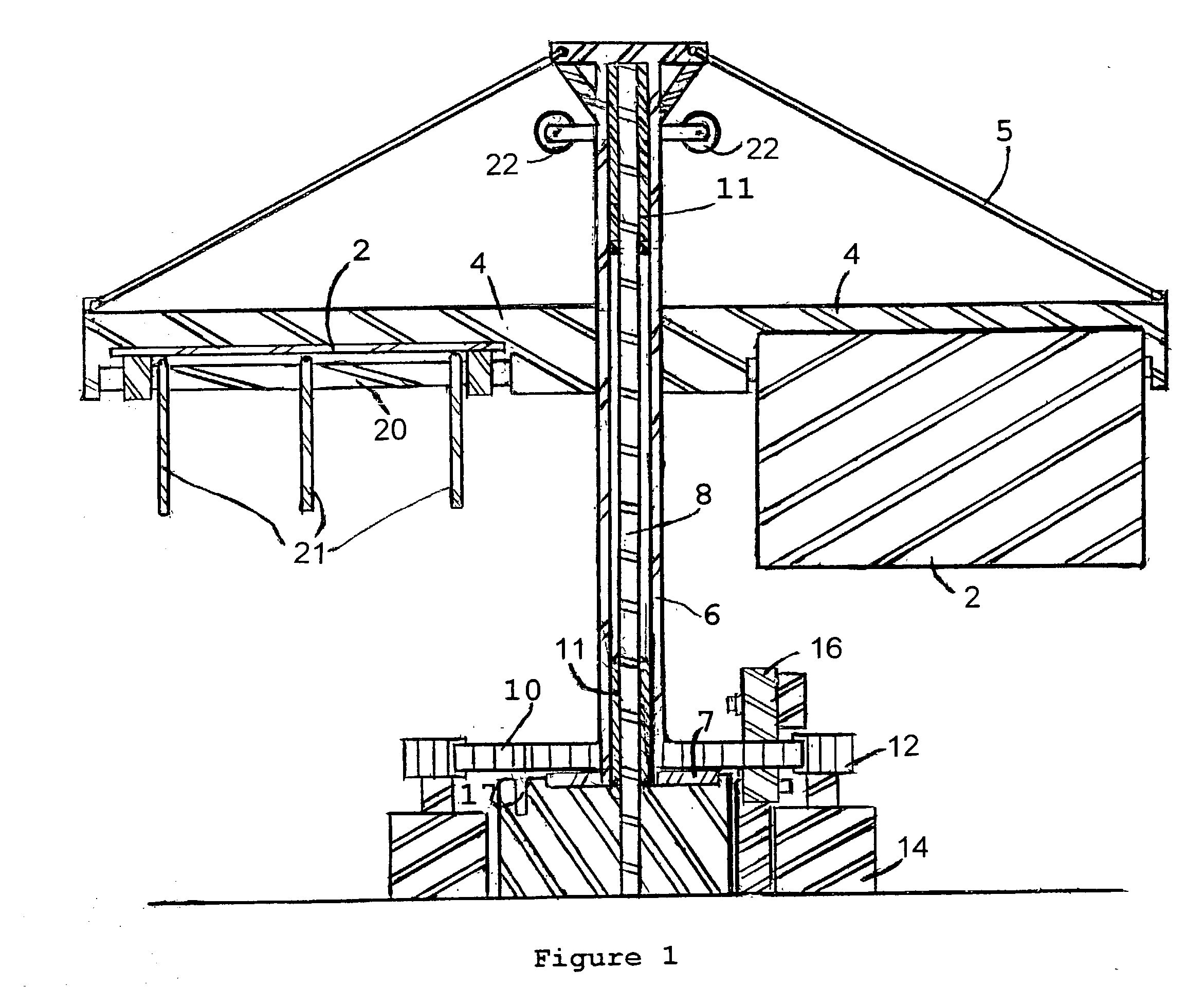
[0033] The principle of leverage is exceedingly powerful. Whatever force is exerted on the Wind blocking means is multiplied by the distance in feet to the Hub. The Wind blocking means start at 4 feet from the Hub and extends out to 76 feet from the Hub. It extends vertically 30 feet high. The dimensions of the wind blocking means on this turbine is 76 feet minus the 4 feet which is 72 feet by 30 feet high and this is 2160 total square feet of area.

[0034] To calculate the leverage, take the one-foot wide column 30 feet high and you have 30 square feet of area. Then multiply that by the pounds per square foot of force on the Wind blocking means. The following example uses a force of 0.2154 pounds per square foot on the Wind blocking means. This results in 6.462 foot pounds of force on that one-foot by 30-foot column. This 6.462 number is multiplied by the 76 foot distance to the Hub and that results in 491 foot pounds of torque on the Hub.

[0035] Here is how the wind force of 0.2154 p...


PUM


Abstract

The invention is a vertical axis wind turbine that utilizes leverage to compound the force from the wind, thereby creating exstordinary power, enough to turn a plurality of generators, thereby reducing the cost per kilowatt of electricity. It has wind blocking means that when struck by the wind from behind they shift to a position to block the wind to absorb energy from the wind thereby causing the turbine to revolve. At the same time, the wind blocking means on the opposite side of the turbine are being struck by the wind on their front leading edge causing them to rotate up to a position where they do not block wind. The result is that one half of the turbine is always being driven by the wind to cause rotation while the opposite side of the turbine is always allowing wind to pass through it. It doesn't matter which direction the wind is coming from.

Description

PATENTS WITH VERTICAL DRIVE OR WHEEL TYPE MACHINES[0001] The early examples of vertical drive wheel type wind machines are as listed. U.S. Pat No. 250,806 in 1881 to Hamel; U.S. Pat. No. 5,88,572 in 1897 to Hardaway; U.S. Pat. No. 863,715 in 1907 to Higby; U.S. Pat. No. 864,789 in 1907 to Kickbush; U.S. Pat. No. 1,234,405 in 1917 to Solomon and U.S. Pat. No. 1,382,591 in 1921 to Akermann.PATENTS WITH WALLS DEFLETORS OR SHIELDS[0002] The patents that applicant references that had walls, deflectors or shields to block the wind from striking on one half of the wheel are.[0003] U.S. Pat. No. 1,523,295 by Ryan in 1925 and U.S. Pat. No. 1,615,675 by Bender in 1927 and U.S. Pat. No. 1,935,097 by Nelson in 1933 and U.S. Pat. No. 3,970,409 by Luchuk in 1976 and U.S. Pat. No. 4,035,658 by Diggs 1977 and U.S. Pat. No. 4,571,152 by Tater in 1986 and U.S. Pat. No. 4,834,610 by Bond III in 1989 and U.S. Pat. No. 4,269,563 and U.S. Pat. No. 5,038,049.[0004] Wind turbines provide an important sourc...

Claims


Application Information

Patent Timeline
IPC IPC(8): F03D3/06
CPCF03D3/067Y02E10/74F05B2240/218F05B2240/40F03D9/25F03D15/10
Inventor PAGE, JOHN S. JR.
Owner PAGE JOHN S JR
Why Eureka
Try Eureka