

Flywheel arrangement for engine
- Summary
- Abstract
- Description
- Claims
- Application Information
AI Technical Summary
Problems solved by technology
Method used
Image

Examples
first embodiment
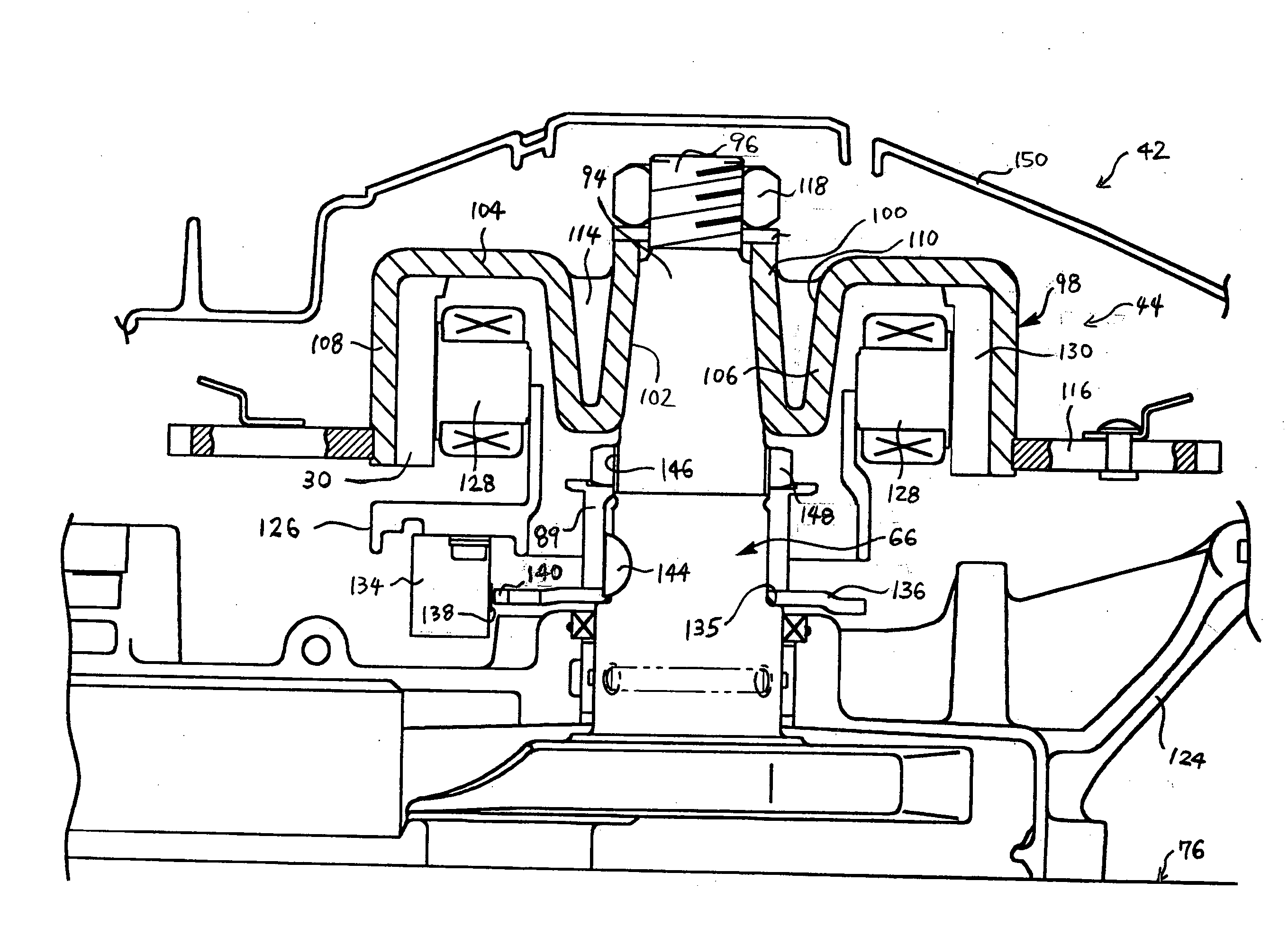
[0040] With reference to FIG. 3, the flywheel arrangement 44 configured in accordance with a first embodiment is described below.
[0041] The crankshaft 56 preferably is tapered upward at a top end area thereof to form a tapered portion 94. In the illustrated embodiment, the uppermost end of the crankshaft 56 is threaded to form an upper threaded portion 96. A diameter of the upper threaded portion 96 is slightly smaller than a diameter of the thinnest part of the tapered portion 94. A flywheel 98 is coupled with the tapered portion 94.
[0042] The flywheel 98 preferably is generally shaped as a reversed circular ashtray and comprises a hub portion 100 and a wheel portion 104 both of which are unitarily formed with each other. The hub portion 100 and the wheel portion 104 preferably have approximately the same thickness. The hub portion 100 is disposed at a center of the flywheel 98 and forms an opening that is tapered upward. The hub portion 100 is put onto the tapered portion 94. The ...
second embodiment
[0065] A crankshaft 167 in this embodiment, does not have the foregoing upper and lower threaded portions 96, 146 (FIG. 3). A straight portion 170 of the crankshaft 167 extends upward to the top end from the portion located above the step 135. Thus, a diameter of the straight portion 170 is larger than the diameter of the straight portion 156 in the
[0066] A flywheel 168 of this embodiment has a shape similar to the flywheel 162 of the FIG. 4except for the hub portion 164. The hub portion 164 of the flywheel 168 is longer than the hub portion 164 of the flywheel 162 and the bottom end of the hub portion 164 directly abuts the top end of the drive pulley 89.
[0067] A fastener tightly affixes the flywheel 168 onto the straight portion 170 of the crankshaft 167. In this embodiment, the fastener is a bolt 172. A bolt hole 174 is made at a center top area of the straight potion 170. A relatively large washer 176 is used such that the washer 176 extends over the top end of the crankshaft 16...
fourth embodiment
[0069] With reference to FIG. 6, a further modified flywheel arrangement 182 configured in accordance with the present invention is described.
PUM
 Abstract
Description
Claims
Application Information