A.C. motor-inverter integrated drive unit

a technology of motor-inverter and drive unit, which is applied in the direction of dc-ac conversion without reversal, association with control/drive circuit, cooling/ventilation arrangement, etc., can solve the problems of increasing the length between the output terminal and the input terminal of the power driver of the inverter, generating various noises, and considerable heat loss

Active Publication Date: 2004-05-13
NISSAN MOTOR CO LTD
View PDF4 Cites 55 Cited by
  • Summary
  • Abstract
  • Description
  • Claims
  • Application Information

AI Technical Summary

Problems solved by technology

However, this arrangement tends to cause increase in length between output terminals of power drivers of the inverter and input terminals of stator coils of the a.c. motor.
Thus, connection of each output terminal of the inverter to corresponding input terminal of the a.c. motor needs an elongate wiring member, which brings about a considerable heat loss caused by an increased electric resistance possessed by the wiring member.
Besides the heat loss, the elongate wiring member causes generation of various noises.
However, due to its inherent construction, employment of the cooling passage in each of the motor and the inverter causes a bulky arrangement of a cooling system.
This means that the cooling system needs a larger or bulky size.

Method used


Image

  • A.C. motor-inverter integrated drive unit
  • A.C. motor-inverter integrated drive unit
  • A.C. motor-inverter integrated drive unit

Examples


first embodiment

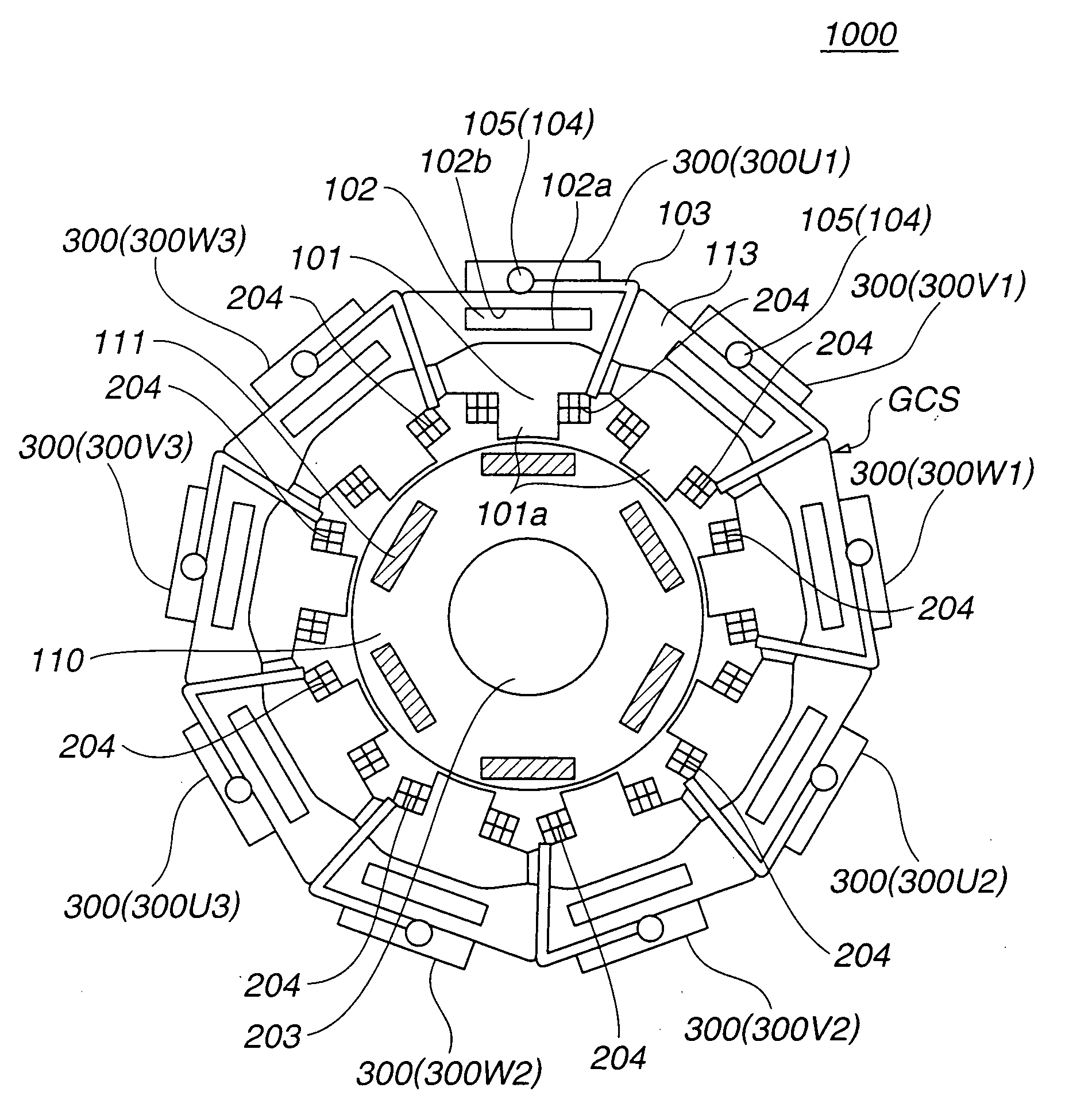
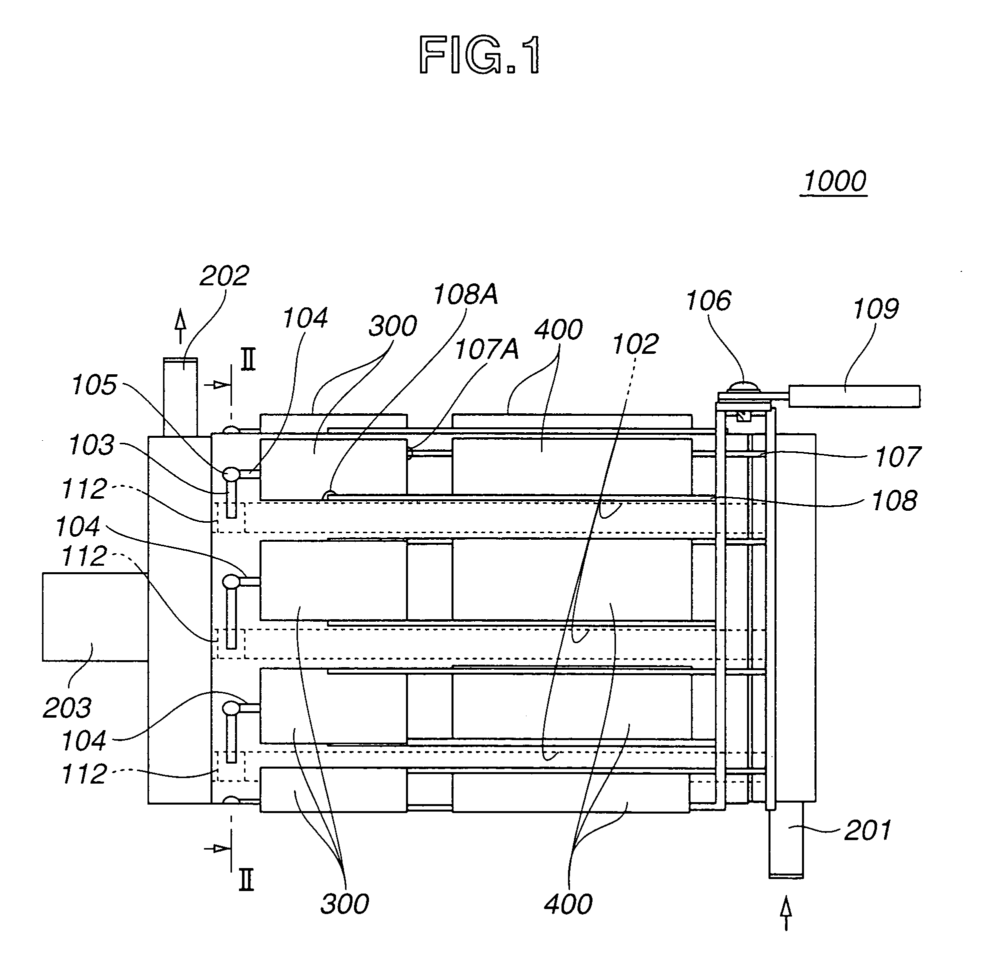
[0016] Referring to FIGS. 1 to 3, there is shown an a.c. motor-inverter integrated drive unit 1000 which is the present invention.

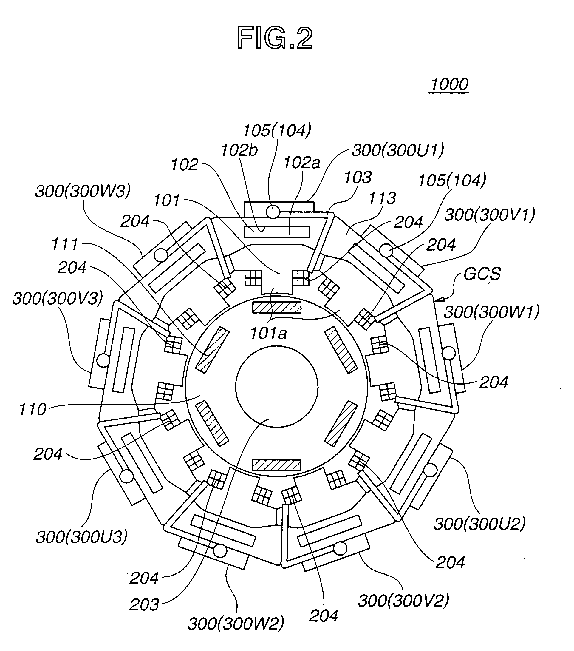
[0017] An a.c. motor employed in this embodiment is of a so-called inner rotor type a.c. motor. More specifically, the motor is of a concentrated winding magnet embedded type three-phase alternating current motor.

[0018] As is seen from FIGS. 1 and 2, the a.c. motor comprises a rotor 110 which is concentrically connected to a motor rotation shaft 203 to rotate therewith.

[0019] As is seen from FIG. 2, rotor 110 has a plurality of magnets 111 embedded therein. The plurality of magnets 111 are arranged around motor rotation shaft 203 at evenly spaced intervals.

[0020] Around rotor 110, there are arranged, at evenly spaced intervals, nine stator cores 101 which constitute a generally cylindrical stator structure "GCS".

[0021] As will be described in detail hereinafter, these stators cores 101 have respective stator coils 204 mounted thereon, which are respective...

second embodiment

[0046] Referring to FIGS. 4 and 5, there is shown an a.c. motor-inverter integrated drive unit 2000 which is the present invention.

[0047] Since the integrated drive unit 2000 of this second embodiment is similar in construction to that 1000 of the above-mentioned first embodiment, only portions or parts which are different from those of the first embodiment 1000 will be described in detail in the following.

[0048] As is seen from FIG. 4, a land portion 112' for each cooling passage 102 is somewhat larger than that 112 of the above-mentioned first embodiment 1000. As is described hereinabove, the land portion 112' is a means for making a watertight sealing of a part of each cooling passage 102.

[0049] As is seen from FIG. 5, in the second embodiment 200, a wiring member 103' from each power switching element 300 is connected to a stator coil 204 that is positioned next to a stator coil 204 that is closest to the power switching element 300. In other words, in this second embodiment 200...

third embodiment

[0056] Referring to FIG. 6, there is shown an a.c. motor-inverter integrated drive unit 3000 which is the present invention.

[0057] As is seen from the drawing, in this embodiment, the concept of the invention is applied to a so-called outer rotor type a. c. motor. That is, an annular rotor 110 having a plurality of magnets 111 embedded therein is arranged to rotate about a generally cylindrical stator structure "GCS". Cylindrical stator structure "GCS" comprises nine stator cores 101, nine main drive upper / lower arm power switching elements 300 and nine stator coils 204. These elements 101, 300 and 204 are evenly installed in nine blocks in substantially same manner as in case of the first embodiment 1000. That is, each block contains therein one stator core 101, one power switching element 300 and one stator coil 204. However, unlike in case of the first and second embodiments 1000 and 2000, the power switching element 300 of each block is arranged at a radially inside position. Be...


PUM


Abstract

An a.c. motor-inverter integrated drive unit comprises an a.c. motor powered by an alternating current. The motor includes a rotor rotatable about a rotation axis, a plurality of stator cores arranged about the rotation axis at evenly spaced intervals to constitute a cylindrical stator structure, a plurality of stator coils disposed on the stator cores respectively and a plurality of cooling passages formed in the stator cores respectively. An inverter is combined with the motor. The inverter converts a direct current to an alternating current and includes a plurality of power drivers which are arranged on the stator cores respectively. Wire members are used for connecting the power drivers and the stator coils respectively.

Description

[0001] 1. Field of the Invention[0002] The present invention relates in general to drive units of a type including an alternating current motor (which will be referred to a.c. motor hereinafter) and more particularly to a so-called a.c. motor-inverter integrated drive unit in which an a.c. motor and an inverter are integrally combined.[0003] 2. Description of Related Art[0004] One of the above-mentioned integrated drive units is shown in Japanese Laid-Open Patent Application (Tokkai) 2000-166176. In this unit, elements of the inverter are concentrated on an upper portion of the a.c. motor. However, this arrangement tends to cause increase in length between output terminals of power drivers of the inverter and input terminals of stator coils of the a.c. motor. Thus, connection of each output terminal of the inverter to corresponding input terminal of the a.c. motor needs an elongate wiring member, which brings about a considerable heat loss caused by an increased electric resistance ...

Claims


Application Information

Patent Timeline
Patent Type & Authority Applications(United States)
IPC IPC(8): H02K9/02H02K9/19H02K11/00H02K11/04H02M7/48
CPCH02K11/0073H02K11/33
Inventor KANEKO, HIROYUKISHINOHARA, TOSHIRO
Owner NISSAN MOTOR CO LTD
Why Eureka
Try Eureka