Axial flux switched reluctance motor and methods of manufacture

a switched reluctance motor and axial flux technology, applied in the direction of dynamo-electric machines, electrical apparatus, magnetic circuits, etc., can solve the problems of complex copper windings of coils, noise of cylindrical switched reluctance motors, and loss of copper, so as to minimize the use of electrical steel, minimize the use of copper, and simplify the effect of windings

Inactive Publication Date: 2010-11-25
MSI MACHINEERING SOLUTIONS
View PDF15 Cites 54 Cited by
  • Summary
  • Abstract
  • Description
  • Claims
  • Application Information

AI Technical Summary

Benefits of technology

[0011]Magnetically induced axial loads are neutralized, use of electrical steel is minimized and the windings are simplified and minimizing use of copper.
[0012]In one aspect of the invention, an axial flux switched reluctance motor comprises: a rotor shaft having an axis; a rotor disc supported along the rotor shaft and having a plurality of rotor poles fit to a periphery thereof and spaced circumferentially thereabout; one or more axially arranged stator elements spaced circumferentially about the periphery of the rotor disc, each stator element having a back iron portion and pair of stator poles extending radially inward from the back iron for axially straddling the rotor disc and forming axial air gaps between each stator pole and the rotor disc, the back iron portion spaced radially outwards from the periphery for forming an annular slot between the stator elements and the rotor disc; and a stator coil fit to each of the annular slots, wherein a switching on of the stator coil energizes the pairs of stator poles for forming an axial and radially inward flux path for attracting circumferentially adjacent rotor poles to rotate the rotor disc and rotor shaft for moving the rotor poles inline with the energized pair of stator poles for minimizing the flux path before switching off of the stator coil.
[0013]In another aspect of the invention, a method of manufacturing an axial flux switched reluctance motor comprises: fitting a plurality of rotor poles to a rotor disc and spacing each of the rotor poles circumferentially about a periphery thereof; mounting one or more of the rotor discs axially along a rotor shaft rotatably mounted in a motor housing; supporting at least one stator element in the motor housing, arranging at least one pair of stator poles of the at least one stator element axially to straddle the rotor disc for forming dual axial air gaps therebetween wherein the stator element connects each stator pole of each pair of stator poles with a back iron portion, and spacing the back iron portion radially outwards from the periphery of the rotor disc for forming a slot therebetween; and fitting a stator coil to each slot for each pair of stator poles and each stator coil adapted for electrical coupling for switched reluctance control wherein upon a switching on of each stator coil energizes its respective pairs of stator poles for forming an axial and radially inward flux path for attracting circumferentially adjacent rotor poles to rotate the rotor disc and rotor shaft for urging the rotor poles inline with the energized pair of stator poles for minimizing the flux path.

Problems solved by technology

Copper windings of the coils are intricate, being wound about discrete poles and having ineffective coil-end connectors to the next pole contributing to copper losses.
Further, cylindrical switched reluctance motors are plagued by noise as radial flexure of the machine housing.
It is known that air gap spacing can vary between the upper and lower U-shaped stators resulting in differential attractive forces and causing an axial loading on the rotor.
Further, the winding of each rotor and stator are conventional and therefor complex, being a series of windings about discrete poles and having ineffective coil-end connectors to the next pole and so on.

Method used


Image

  • Axial flux switched reluctance motor and methods of manufacture
  • Axial flux switched reluctance motor and methods of manufacture
  • Axial flux switched reluctance motor and methods of manufacture

Examples


Embodiment Construction

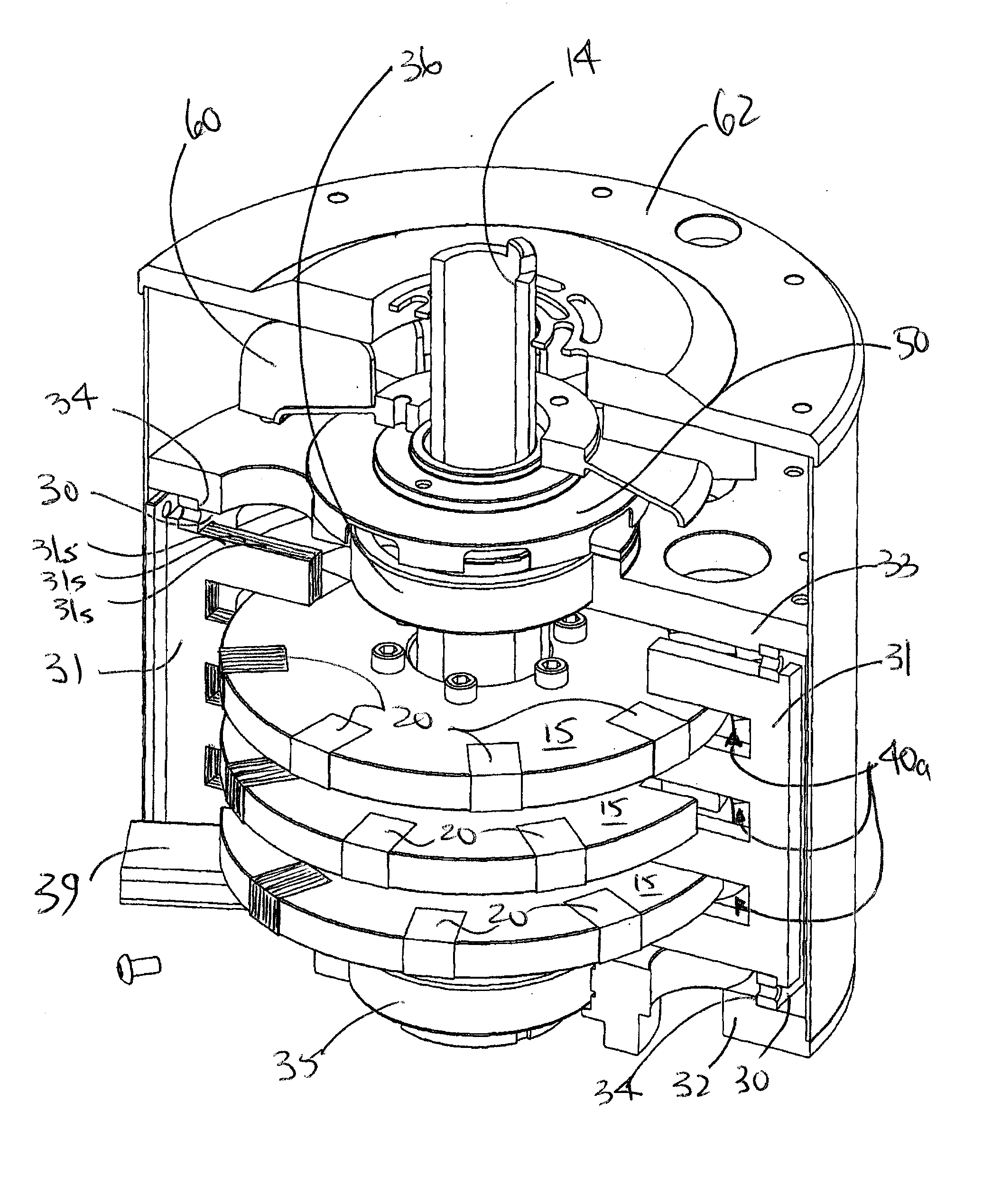
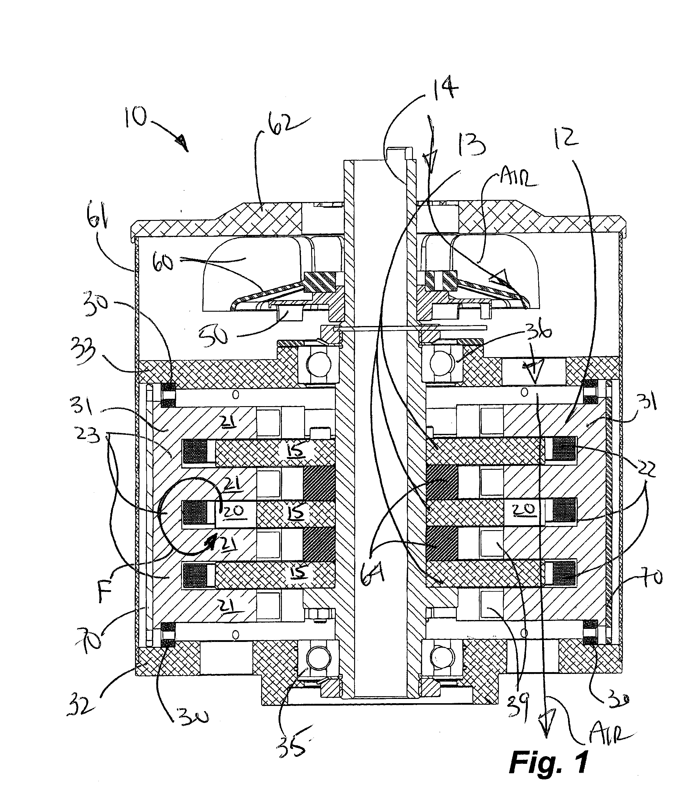
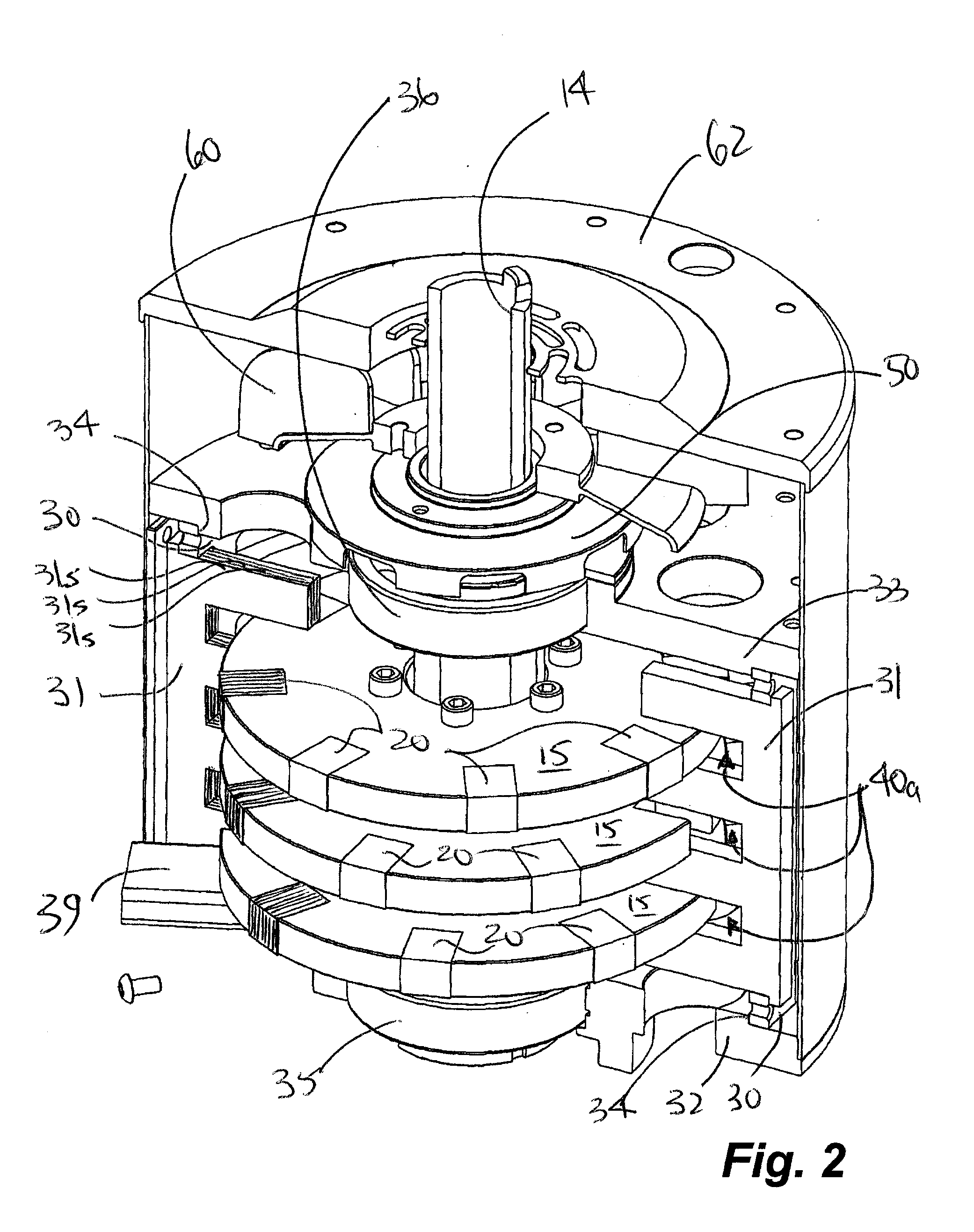
[0029]As shown in cross-section FIG. 1 and fully assembled in FIG. 3, an axial flux electromotive generating device or motor 10 using switch reluctance control has a stator arrangement 12 and a rotor 13. The principles of switched reluctance motors are known to those of ordinary skill in the art. Applicant has provided a heretofore unknown and advantageous arrangement of stator arrangement 12 and rotor 13.

[0030]The term “switched reluctance” has now become the popular term for a class of electric machine. The topology of conventional switched reluctance motors (SRM) implement phase coils mounted around diametrically opposite stator poles which are radially spaced about a rotor. A conventional SRM rotor has a plurality of radially extending poles. Energizing of a stator phase will cause a rotor pole to move into alignment with corresponding stator poles, thereby minimizing the reluctance of the magnetic flux path. Rotor position information is used to control energizing of each phase...


PUM

PropertyMeasurementUnit
magnetic fieldaaaaaaaaaa
axial heightaaaaaaaaaa
radial depthaaaaaaaaaa

Abstract

An axial flux switched reluctance motor utilizes one or more rotor discs spaced along a rotor shaft, each rotor disc having a plurality of rotor poles spaced along the periphery thereof. Stator elements are distributed circumferentially about the rotor discs and form pairs of radially extending stator poles for axially straddling the rotor discs. Stator coils as switched on to energize pairs of stator poles for forming an axial and radially inward flux path for rotating the rotor poles for minimizing the flux path before switching off the stator coil. Two or more rotor discs can be rotationally indexed for providing two or more motor phases. In manufacture, rotor discs and circumferentially extending stator coils about the periphery of each rotor disc are fit to a stator housing. Each stator element is then fit radially through the stator housing and secured thereto for straddling the rotor discs.

Description

CROSS-REFERENCE TO RELATED APPLICATION[0001]This application claims the benefit of U.S. Provisional Patent application Ser. No. 60 / 804,564, filed Jun. 12, 2006, the entirety of which is incorporated herein by reference.FIELD OF THE INVENTION[0002]The present invention relates to axial flux switched reluctance motors and more particularly to motors using a one or more rotor discs, circumferentially-wound coils and circumferentially-spaced stators arranged axially to straddle each of the rotor discs forming axial air gaps.BACKGROUND OF THE INVENTION[0003]Conventional cylindrical switch reluctance (SR) motors (SRM) typically utilize rotors with poles extending along the rotor and corresponding stators extending axially along the rotor. The circumferential flux path of such motors is along a significant angular portion of the motor: in a 6 pole rotor being ½ of the circumference of the motor and in a 12 pole motor, being ¼ of the away around contributing to iron losses. Copper windings ...

Claims


Application Information

Patent Timeline
Patent Type & Authority Applications(United States)
IPC IPC(8): H02K19/06H02K16/00H02K15/02
CPCH02K1/145H02K1/185Y10T29/49012H02K29/08H02K2201/12H02K19/103
Inventor TESSIER, LYNN P.DOYLE, JOHN P.WEBER, JAMES L.
Owner MSI MACHINEERING SOLUTIONS
Why Eureka
Try Eureka