Holder for digital sensors for dentistry

a technology for digital sensors and holder holders, applied in the field of holder holders for digital sensors for dentistry, can solve the problems of limited universal application of this holder, and the construction does not allow the universal application of the most diverse sensors

Active Publication Date: 2004-05-20
KERRHAWE
View PDF9 Cites 31 Cited by
  • Summary
  • Abstract
  • Description
  • Claims
  • Application Information

AI Technical Summary

Problems solved by technology

Although it is already suggested here to use different formats, the universal application of this holder is limited

Method used


Image

  • Holder for digital sensors for dentistry
  • Holder for digital sensors for dentistry
  • Holder for digital sensors for dentistry

Examples


Embodiment Construction

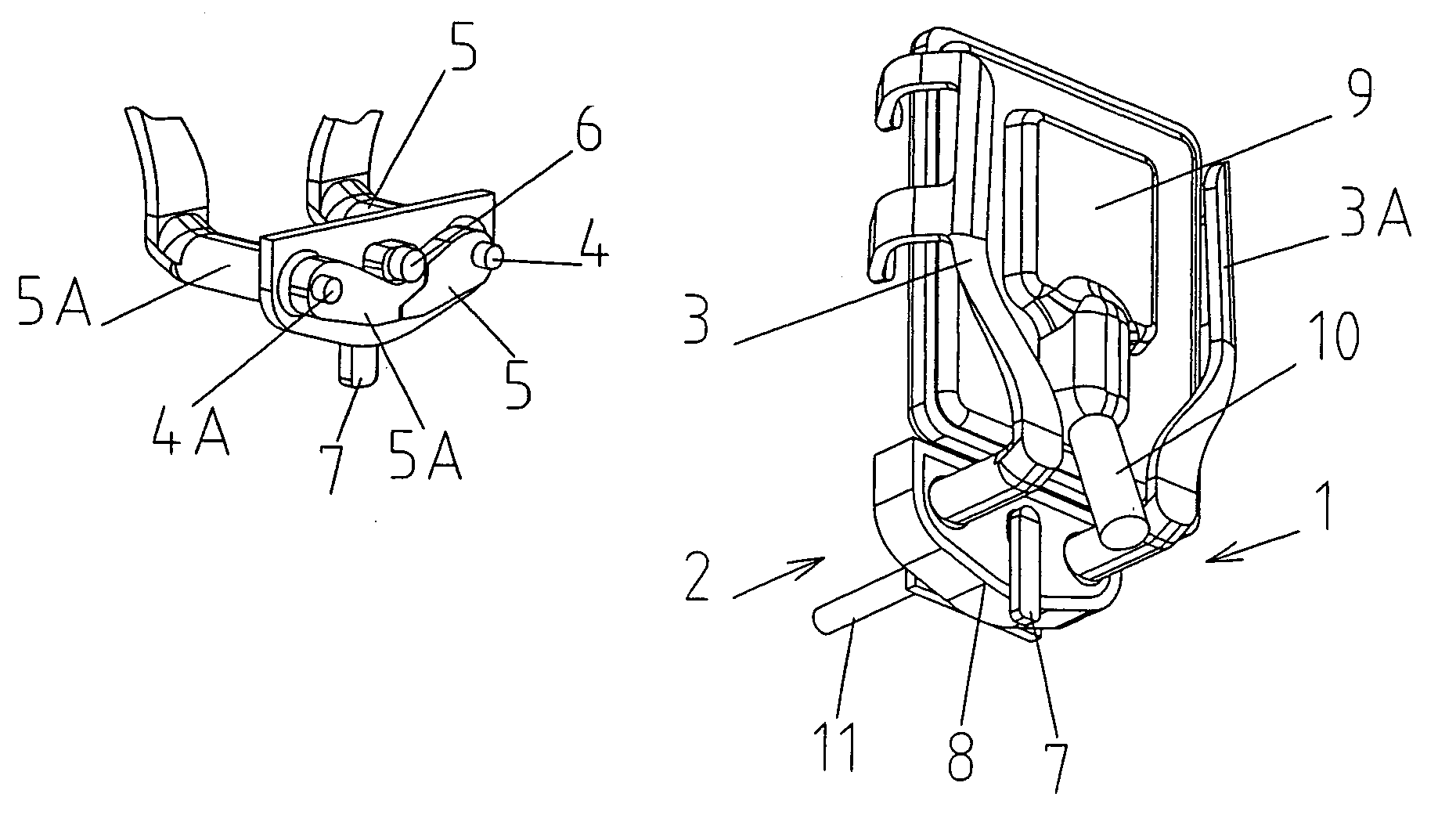
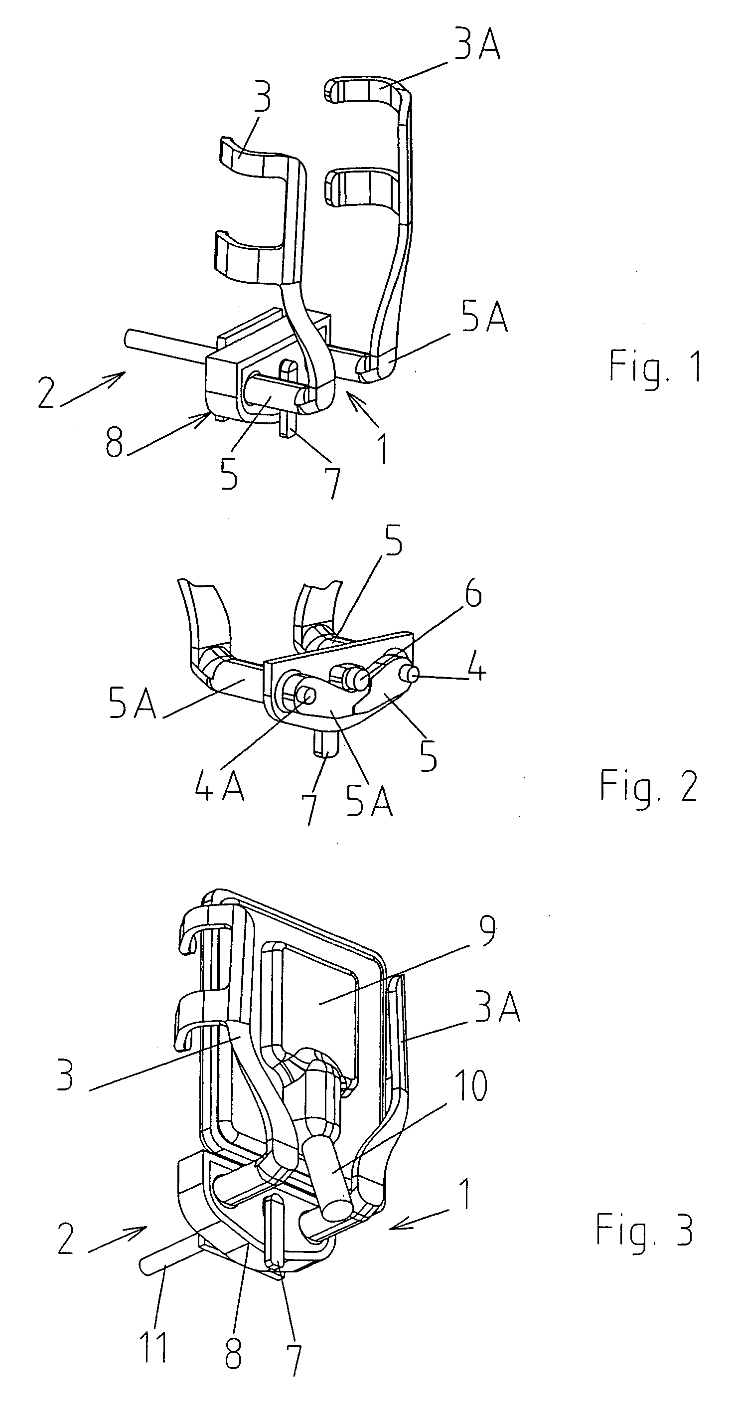
[0017] FIGS. 1 to 3 show a first exemplifying embodiment of a sensor clamp of a holder where the two arms with the retaining strip are moved in a self-centering manner. Sensor clamp 1 of holder 2 comprises two arms 3 and 3A that are hinged on respective axles 4 and 4A and comprise respective angled levers 5, 5A actuated by a camshaft 6 in such a manner that the levers are pivoted down in FIG. 2 and the arms are thus swung inwards. The camshaft is under the action of a locking lever 7 for unlocking the arms, whereby they are swung to the open position. The camshaft and the levers are arranged in an enclosure 8.

[0018] This holder is particularly suitable for periapical radiographs of the anterior teeth, and it appears in FIG. 3 that the digital sensor 9 with cable 10 is laterally clamped and the arms are designed such that little space is required laterally. Furthermore, it appears in FIG. 3 that the sensor clamp does not project beyond sensor 9.

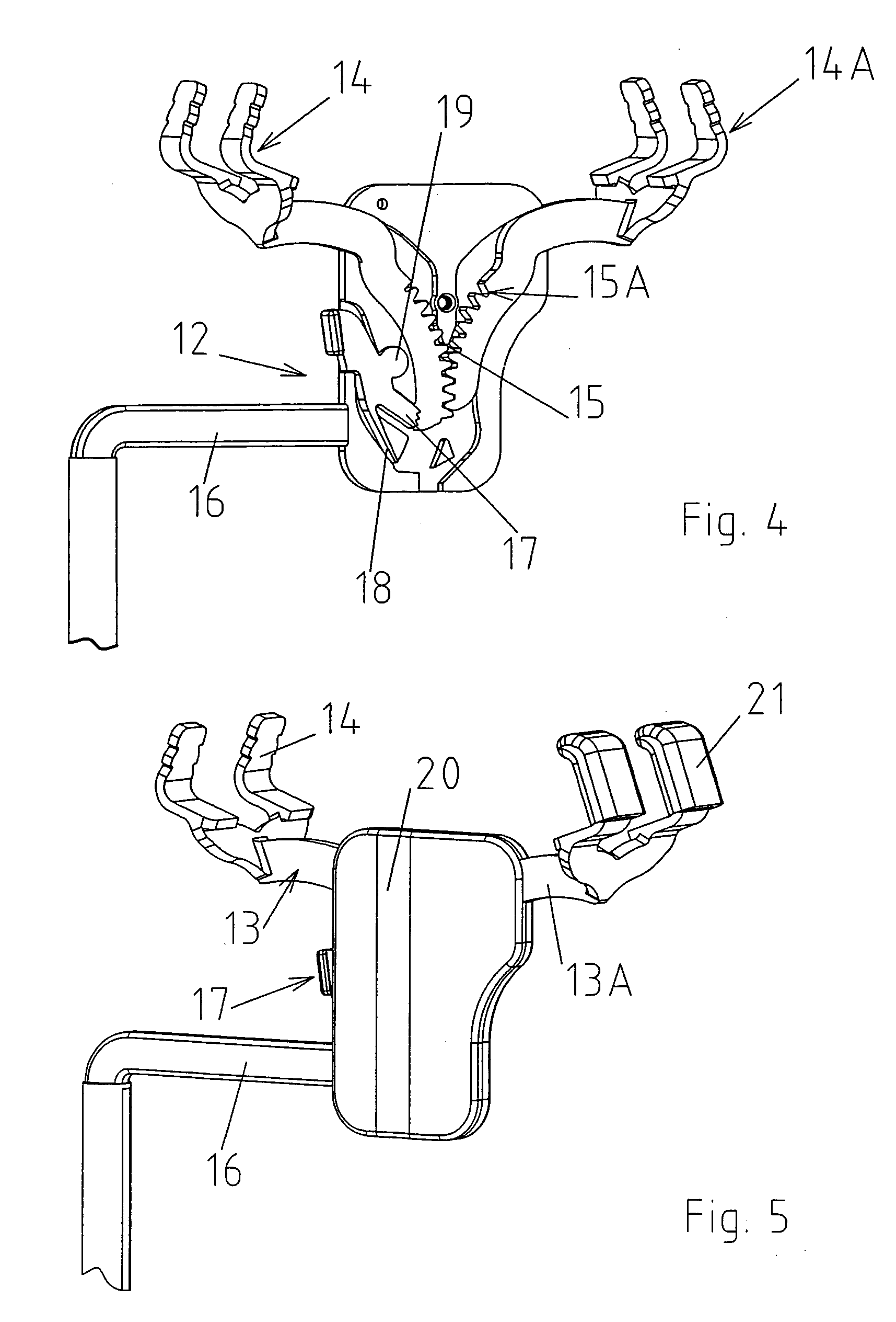
[0019] FIGS. 1 or 3 show a portion 11 o...


PUM


Abstract

In the holder set for digital sensors for dentistry, the holders for each kind of radiograph such as periapical radiographs of front teeth (anterior teeth) and lateral teeth (posterior teeth), on one hand, and bitewing radiographs, on the other hand, can be used for all sensor formats, the sensors being seized in the respective holders in a self-centered manner by two arms independently of their format.

Description

[0001] The present invention refers to a holder set for digital sensors for dentistry, each holder of the set comprising at least one displaceable arm.[0002] Until lately, radiographs have been recorded on X-ray films that have been exposed and subsequently developed. Since X-ray films of this kind have determined standard formats, the sizes of the holders resp. of the clamping portions intended for receiving the X-ray films are standardized too. Up to now, the main problem with regard to such X-ray film holders has been to enable radiographs of the bitewing and of other areas of the teeth with a minimum number of different holders, while the film formats are mostly clamped either transversely or longitudinally.[0003] Recently, a new imaging technique has been developed where digital image sensors are directly connected to a computer by a cable in order to directly display or store the radiographs on the latter.[0004] In contrast to X-ray films, the different digital sensor products...

Claims


Application Information

Patent Timeline
IPC IPC(8): A61B6/14G03B42/04
CPCA61B6/145A61B6/4423
Inventor KILCHER, BEATROLD, MARCO DA
Owner KERRHAWE
Why Eureka
Try Eureka