
Slat wall assembly

Inactive Publication Date: 2004-06-17
UNISLAT
View PDF31 Cites 17 Cited by
  • Summary
  • Abstract
  • Description
  • Claims
  • Application Information

AI Technical Summary

Benefits of technology

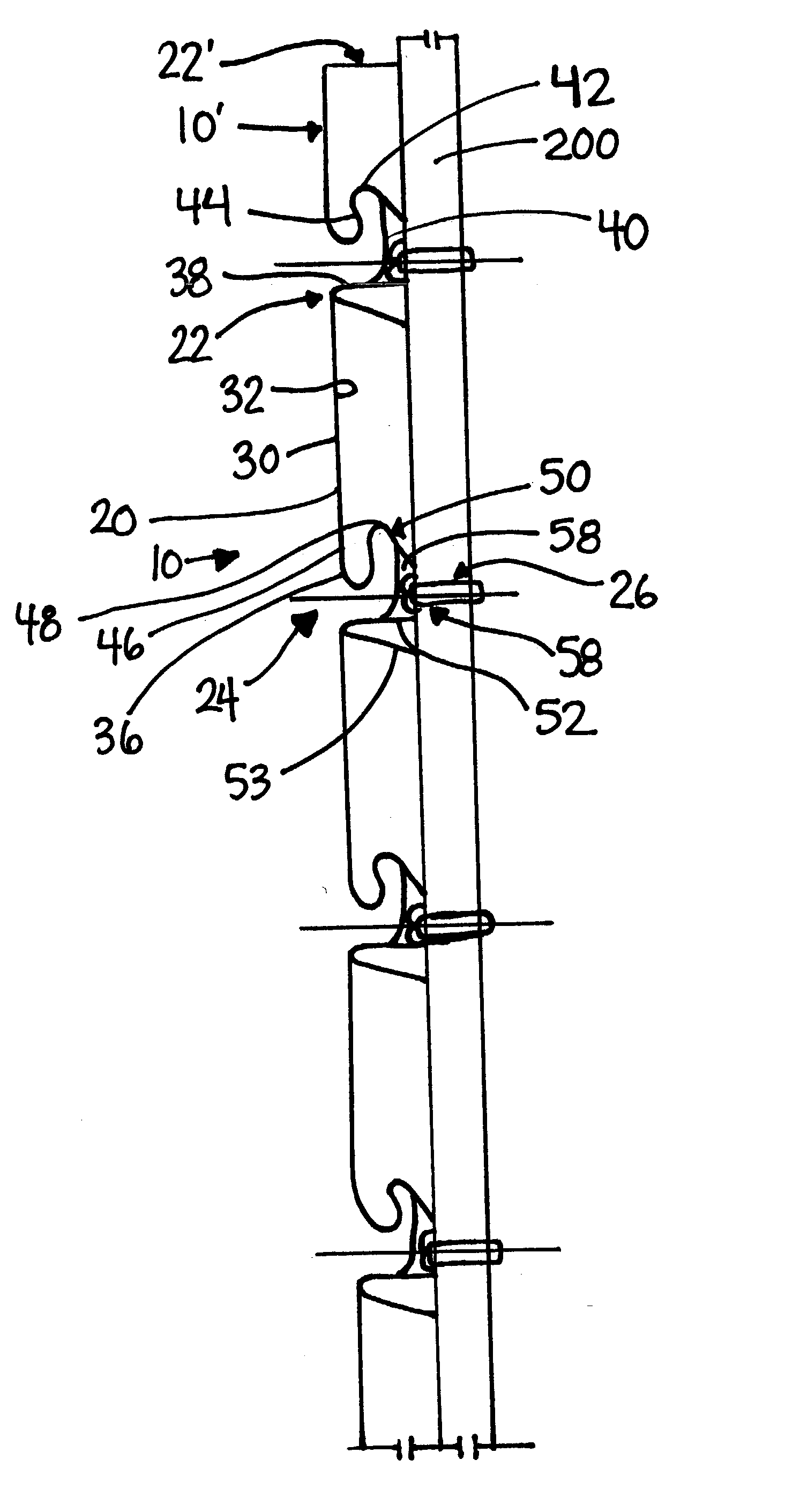
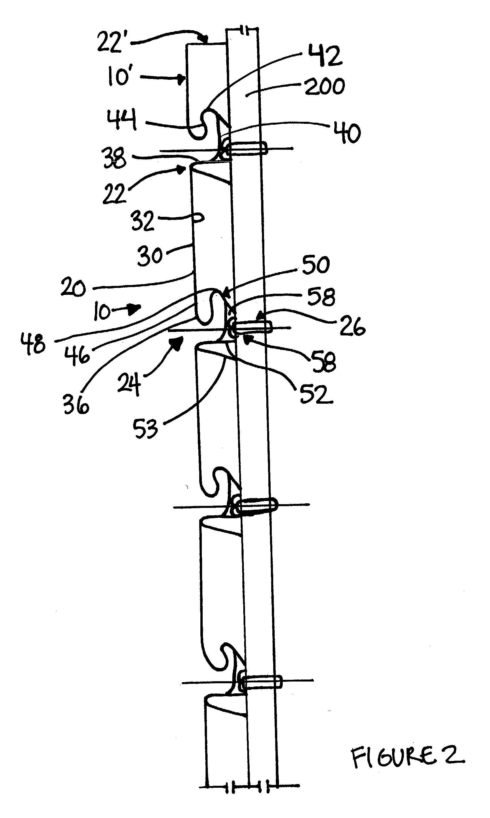
[0011] In another aspect of the invention, the invention comprises a wall assembly formed from a plurality of slats. Each slat comprises a body, an upper flange, and a lower flange. The body includes an upper edge and a lower edge. The upper flange emanates from the upper edge of the body. The lower flange emanates from the lower edge. The upper flange is configured to be insertable into the lower flange of a first slat and lockable therein. This, in turn, facilitates the assembly of a wall assembly through successive insertion of an upper flange of a slat with a lower flange of an adjoining slat.

Problems solved by technology

While such slat walls have become quite popular for the above-identified reasons, a plurality of problems and / or drawbacks exist in association with their use.
For example, among other drawbacks, the frame member is often difficult to properly install.
Moreover, in many prior art designs, slats are difficult to assemble relative to the frame and relative to other slats.
As such, great skill is required to properly install such a slat wall.

Method used


Image

  • Slat wall assembly
  • Slat wall assembly
  • Slat wall assembly

Examples


Embodiment Construction

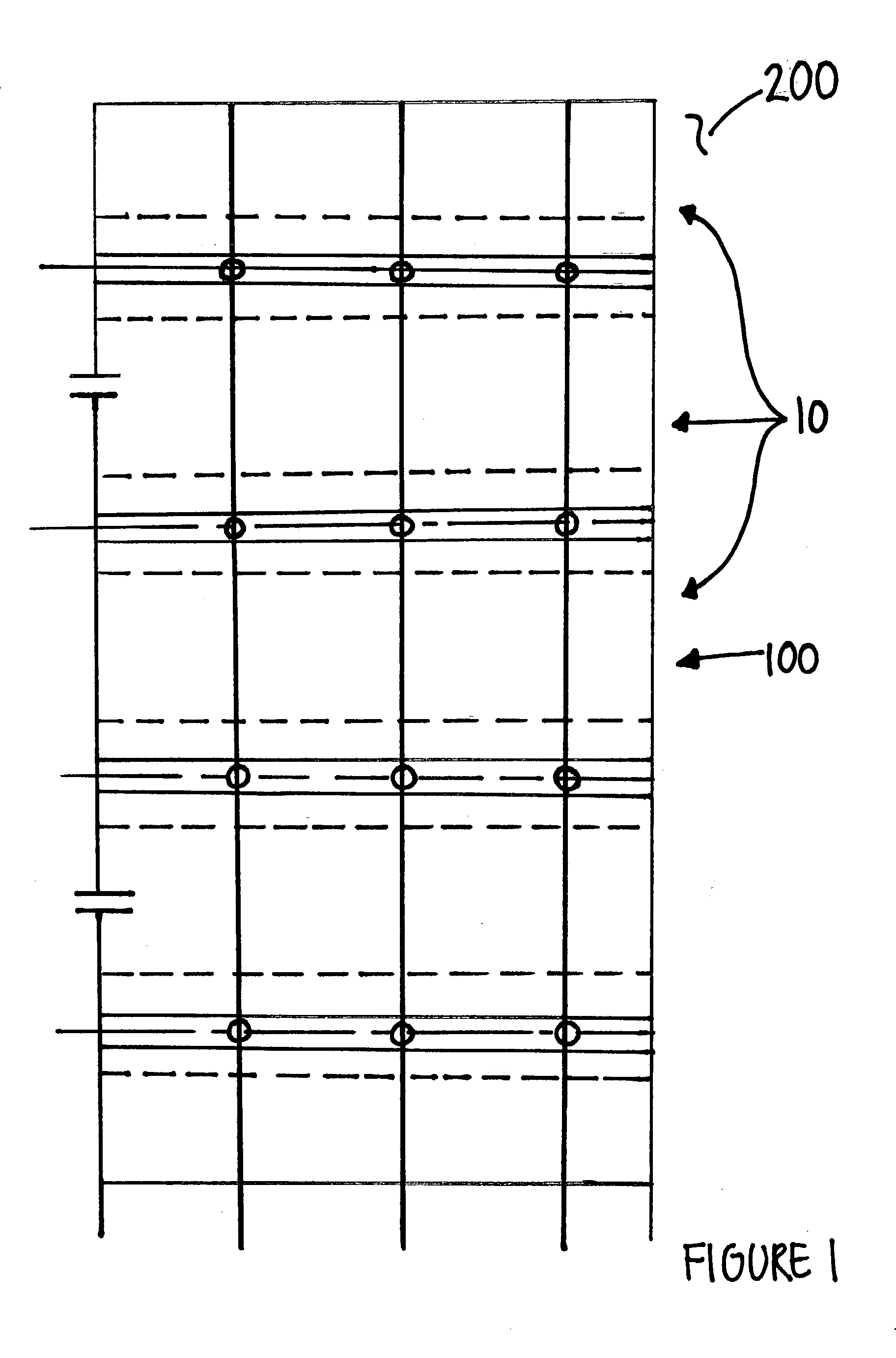
[0031] While this invention is capable of embodiment in many different forms, there is shown in the drawings and will be described herein in detail, one specific embodiment with the understanding that the present disclosure is to be considered as an exemplification of the principles of the invention and is not intended to limit the invention to the embodiment illustrated.

[0032] It will be understood that like or analogous elements and / or components, referred to herein, are identified throughout the drawings by like reference characters. In addition, it will be understood that the drawings are merely representations, and some of the components may have been distorted from actual scale for purposes of pictorial clarity.

[0033] Referring now to FIG. 1, slat wall assembly 100 is shown as generally comprising a plurality of slats 10 which are both mounted to wall 200 and to each other.

[0034] Preferably, the slats comprise an elongated metal material which has been extruded or otherwise fo...


PUM


Abstract

A slat wall assembly comprising a first slat, an attachment assembly, and a second slat. The first slat includes a body and a lower flange. The body includes an upper edge and a lower edge. The lower flange emanates from the lower edge of the body. The attachment assembly is associable with the lower flange of the first slat and facilitates attachment of the first slat to an existing wall. The second slat includes a body and an upper flange. The body includes an upper edge and a lower edge. The upper flange emanates from the upper edge of the body. The upper flange is configured to be insertable into the lower flange of the first slat and retainable therein.

Description

BACKGROUND OF THE INVENTION[0001] 1. Field of the Invention[0002] The invention relates in general to a slat wall system, and, more particularly, to a metal slat wall system having a simplified installation and assembly, to, in turn, facilitate installation and assembly by consumers.[0003] 2. Background Art[0004] Slat walls have been known in the art for many years. Typically, conventional slat walls comprise a plurality of slats and a frame member. The frame member is attached to a wall or outside surface. Subsequently, the slats are attached to the frame member to complete the slat wall. Once complete, users can selectively attach shelving units and other storage and display accessories to the slat wall. Slat walls provide an aesthetically pleasing storage assembly, and, in addition, permit a user to quickly reconfigure and re-deploy the shelving units and other storage and display items which are attached to the slat wall.[0005] While such slat walls have become quite popular for...

Claims


Application Information

Patent Timeline
IPC IPC(8): E04F13/12E04F13/18E04F19/02
CPCE04F13/12E04F13/0864E04F19/02E04F13/18E04F19/066
Inventor KOSCH, PAUL JAMES
Owner UNISLAT
Learn More