Projected fuel dispensing nozzle

Active Publication Date: 2008-01-10
WAYNE FUELING SYST
View PDF11 Cites 10 Cited by
  • Summary
  • Abstract
  • Description
  • Claims
  • Application Information

AI Technical Summary

Benefits of technology

[0019] The first and second nozzle holders may be configured to hold the fuel dispensing nozzles separated by a distance less than 25 cm along a first direction, said first direction being perpendicular to a normal to said side. This arrangement is advantageous since it has been observed that this distance is the maximum distance to achieve less tangling of hoses and less obscured delivery nozzles. In other words the first nozzle holder is positioned adjacent to the second nozzle holder.
[0020] The first and second nozzle holders may be configured to hold the fuel dispensing nozzles separated by a distance less tha

Problems solved by technology

A problem common to prior-art hose handling devices is that fuel hoses may get entangled.
Another problem is that a fuel hose may land in front of a fuel delivery nozzle belon

Method used


Image

  • Projected fuel dispensing nozzle
  • Projected fuel dispensing nozzle
  • Projected fuel dispensing nozzle

Examples


Embodiment Construction

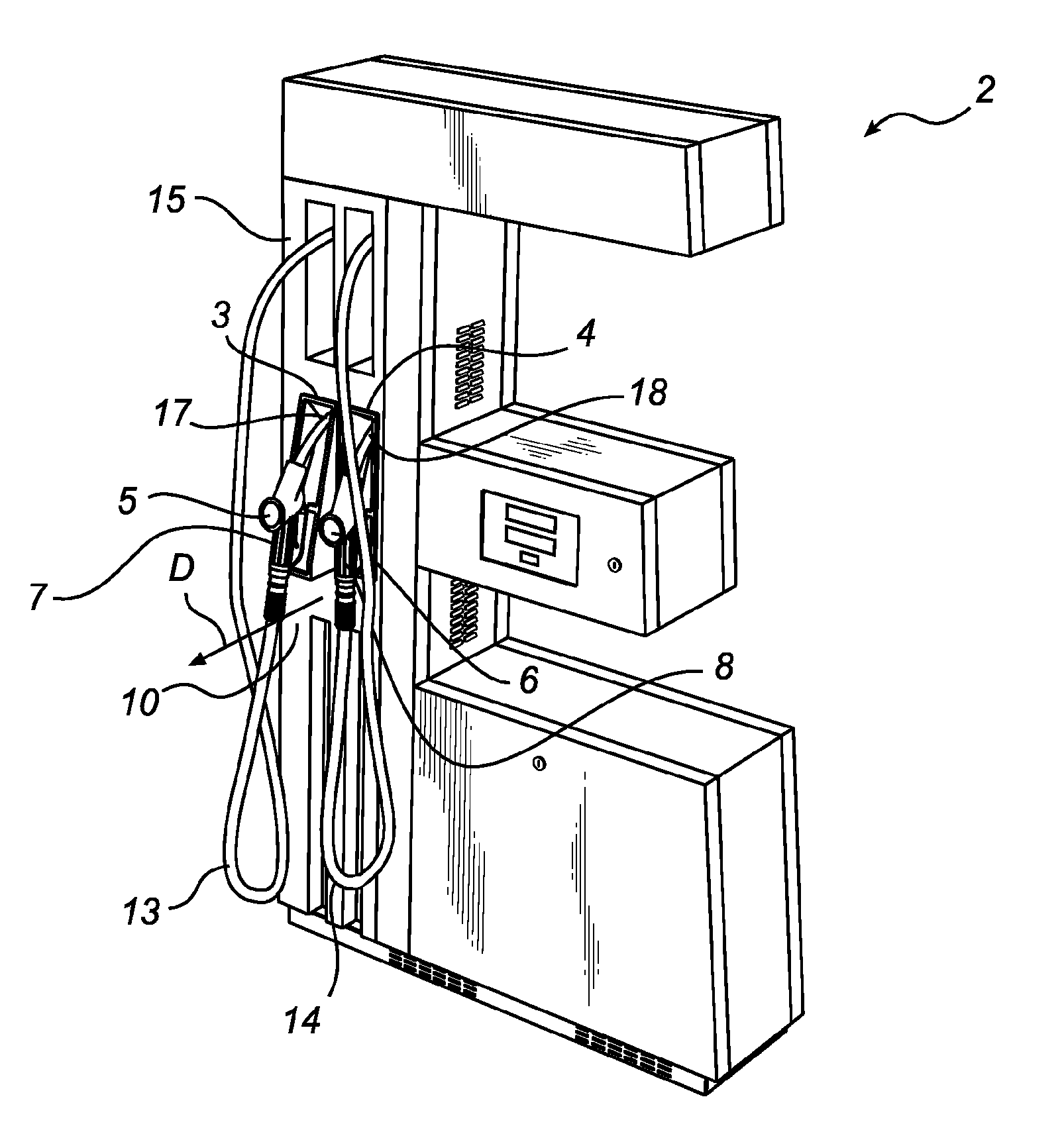
[0031] With reference to FIGS. 1 and 2, a fuel dispensing unit 2 is illustrated having a first fuel hose 13 and a second fuel hose 14. Both hoses 13, 14 are suspended from a top part 15 of the fuel dispenser 2. A first fuel dispensing nozzle 5 has a nozzle outlet 17 for letting out fuel and a handle 7 connected to an end of the first hose 13, and a second fuel dispensing nozzle 6 has a nozzle outlet 18 for letting out fuel and a handle 8 connected to an end of the second hose 14.

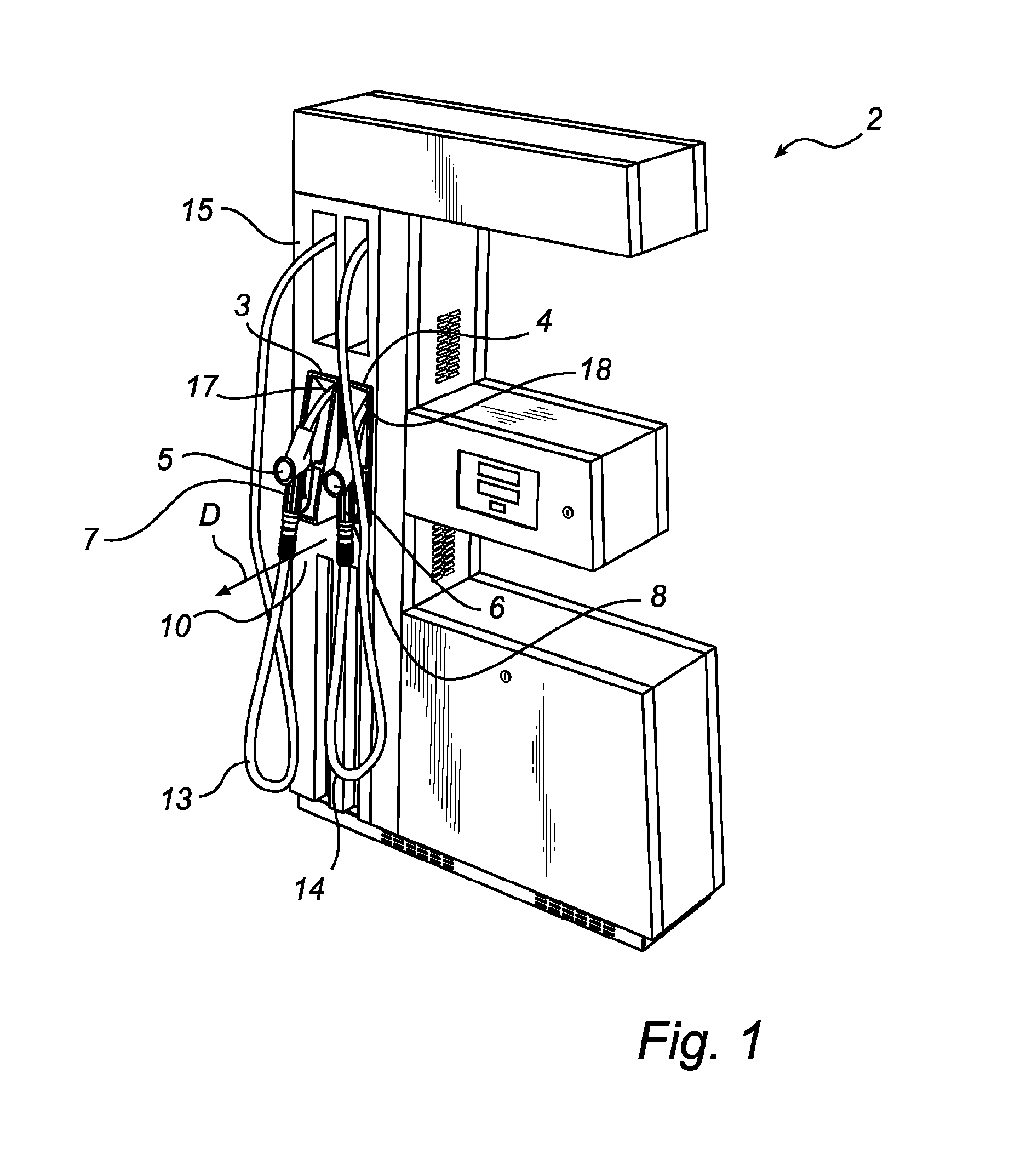
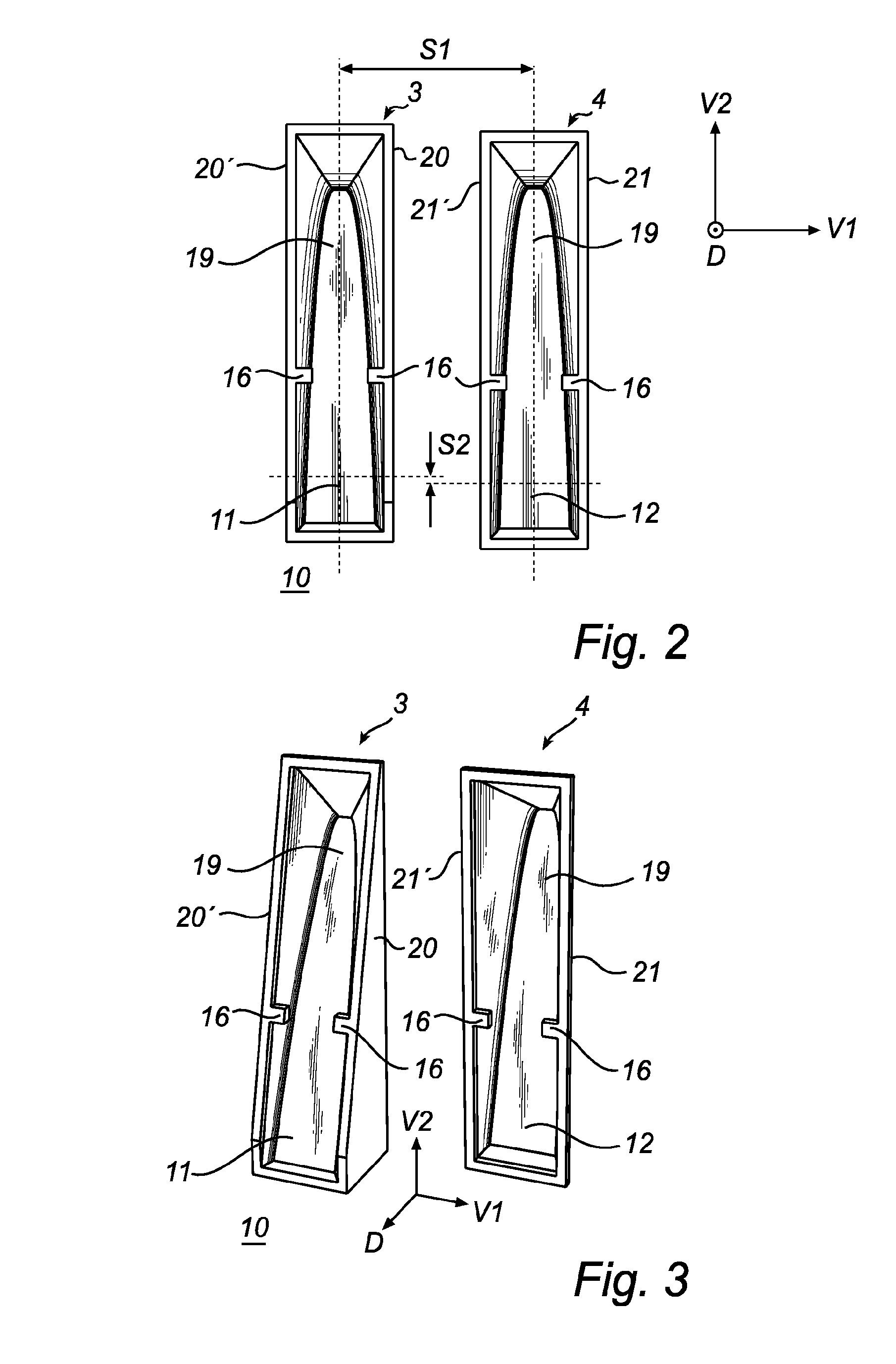
[0032] On a side 10 of the fuel dispensing unit 2 a first nozzle holder 3 and a second nozzle holder 4 are arranged adjacent to each other. When the fuel dispensing unit 2 is not operated, the first dispensing nozzle 5 rests in the first nozzle holder 3 and the second dispensing nozzle 6 rests in the second nozzle holder 4.

[0033] Each nozzle holder 3, 4 comprises a substantially rectangular frame and holding pegs 16 for holding the respective dispensing nozzle 4, 5 and has an upper recess 19 for receiving ...


PUM


Abstract

A fuel dispensing unit for refueling vehicles, said fuel dispensing unit comprising a first nozzle holder (3) for holding a first fuel dispensing nozzle (5), and a second nozzle holder (4) for holding a second fuel dispensing nozzle (6), both nozzle holders (3, 4) being arranged on a common side (10) of the fuel dispensing unit. The first nozzle holder (3) being configured to project, in a direction (D) away from said side (10) of the fuel dispensing unit, at least a part (7) of the first fuel dispensing nozzle (5) in relation to a corresponding part (8) of the second fuel dispensing nozzle (6).

Description

TECHNICAL FIELD [0001] The present invention relates to a fuel dispensing unit comprising a first nozzle holder for holding a first fuel dispensing nozzle, and a second nozzle holder for holding a second fuel dispensing nozzle. Both nozzle holders are arranged on a common side of the fuel dispensing unit. BACKGROUND ART [0002] A fuel dispensing unit typically comprises a pump part standing on the ground, a display part positioned above the pump part and showing the chosen type of petrol, cash readout, volume readout etc, and a column to which one or more petrol hoses are connected. A fuel delivery nozzle is connected at the end of each fuel hose, and each fuel delivery nozzle normally rests in a nozzle boot, or a nozzle holder arranged on a side of the fuel dispensing unit. [0003] When the tank of a vehicle is to be filled up, the driver parks the vehicle beside the fuel dispensing unit and removes the cap of the vehicle's petrol tank. Then the driver selects the desired type of pet...

Claims


Application Information

Patent Timeline
IPC IPC(8): B67D5/12B67D7/04B67D7/12
CPCB67D7/04B67D7/84B67D7/06
Inventor WEMMERT, MARLENE
Owner WAYNE FUELING SYST
Why Eureka
Try Eureka