Linkage system with wear reduction

Active Publication Date: 2008-10-02
RAYTHEON TECH CORP
View PDF28 Cites 8 Cited by
  • Summary
  • Abstract
  • Description
  • Claims
  • Application Information

AI Technical Summary

Benefits of technology

[0006]A linkage system according to the present invention includes a pivot bias assembly at each pivot which removes internal clearances and resultant vibratory wear. This invention is applicable to any linkage that may operate in an unloaded condition.
[0007]The pivot bias assembly includes a cavity which defines an axis transverse to a pivot axis. A piston is biased by a spring located therein to provide a radial load along axis toward the rotation pivot axis to close radial clearances. The spring loaded piston reduces all the radial internal clearances to zero to reduce vibratory wear created by engine vibratory inputs.
[0008]During assembly, the spring and piston are inserted into the piston cavity. The component is aligned with the pi

Problems solved by technology

While unloaded, the linkage may experience undue w

Method used


Image

  • Linkage system with wear reduction
  • Linkage system with wear reduction
  • Linkage system with wear reduction

Examples


Example

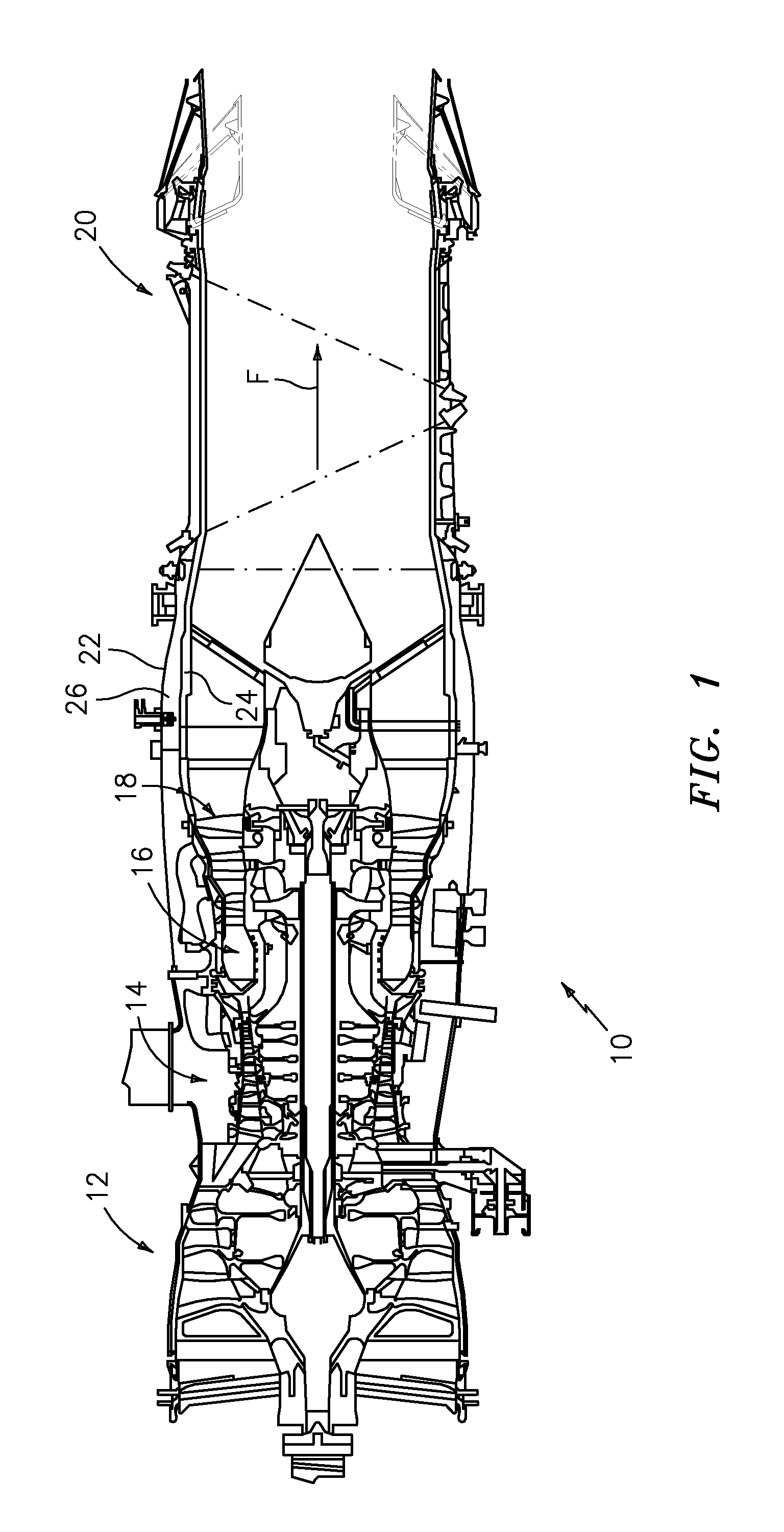
[0021]FIG. 1 schematically illustrates a gas turbine engine 10 which generally includes a fan section 12, a compressor section 14, a combustor section 16, a turbine section 18, and a nozzle section 20. Within and aft of the combustor 16, engine components are typically cooled due to intense temperatures of the combustion core gases.

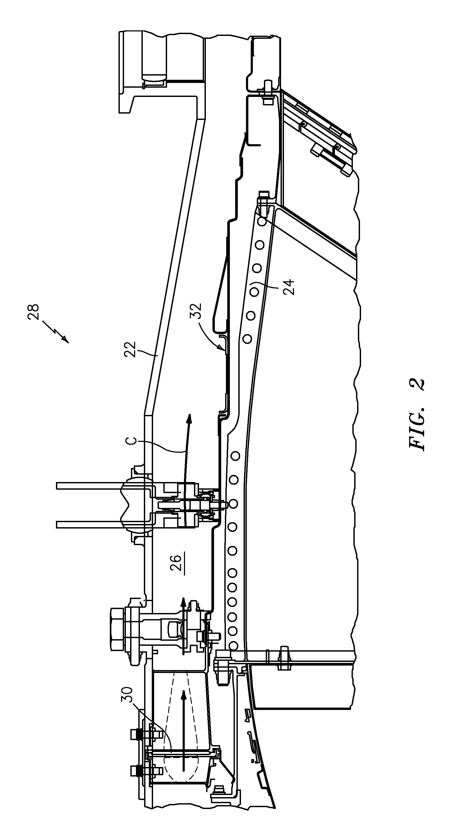
[0022]An outer engine case 22 and an inner cooling liner structure 24 define an annular secondary fan bypass flow path 26. It should be understood that various structure within the engine may be defined by the outer engine case 22 and the inner cooling liner structure 24 to define various cooling airflow paths such as the disclosed fan bypass flow path 26. The fan bypass flow path 26 guides a cooling airflow (illustrated schematically by arrows C; FIG. 2) between the outer engine case 22 and the inner cooling liner structure 24. Cooling airflow C and / or other airflow that is different from the exhaust gas flow (illustrated schematically by arrow F) is typ...


PUM


Abstract

A linkage system includes a pivot bias assembly at each pivot which removes internal clearances and resultant vibratory wear. The pivot bias assembly includes a cavity which defines an axis transverse to the pivot axis. A spring biased piston is located therein to provide a radial load toward the rotation pivot to close radial clearances. The spring loaded piston reduces all the radial internal clearances to zero to reduce vibratory wear created by engine vibratory inputs. An assembly flat is positioned such that the component is assembled in a non-operating angular position such that the spring biased piston is under minimal or no load then the component is rotated into operating position so as to preload the spring biased piston.

Description

RESEARCH OR DEVELOPMENT[0001]This invention was made with Government support under F33657-99-C-1236 awarded by The United States Air Force. The Government has certain rights in this invention.BACKGROUND OF THE INVENTION[0002]The present invention relates to a gas turbine engine, and more particularly to a linkage system which provides a load to each articulating joint to artificially remove internal clearances and reduce vibratory wear when the linkage is in an unloaded condition.[0003]Gas turbine engine exhaust ducts include a liner disposed between the engine exhaust gas path and the engine outer casing or duct. Cooling air is flowed between the cooling liner and duct then discharged over the seals and flaps of the nozzle located at the rear end of the exhaust duct. In order to improve engine operation and performance, exhaust duct cooling air is carefully rationed.[0004]As the engine is subjected to large core pressure gradients at various operating conditions, a rotational flow ...

Claims


Application Information

Patent Timeline
IPC IPC(8): F02K9/66
CPCF01D17/105F01D17/141F01D25/04F02C9/18F02K1/822F02K3/075Y02T50/675F05D2220/36F05D2260/56F05D2260/96F05D2260/52Y02T50/60
Inventor LOFFREDO, CONSTANTINO V.
Owner RAYTHEON TECH CORP
Why Eureka
Try Eureka