Oxygen concentrating device

Inactive Publication Date: 2009-11-12
SANYO ELECTRONICS IND CO LTD
View PDF11 Cites 11 Cited by
  • Summary
  • Abstract
  • Description
  • Claims
  • Application Information

AI Technical Summary

Benefits of technology

[0041]As mentioned above, an oxygen concentrating device in which the assembly is facilitated and the production cost can be reduced is provided according to the present invention. An oxygen concentrating device in which, in addition to increase in the dimensional accuracy, shrinkage hole (depression formed on a surface side etc. of a reinforcement rib to be hereinafter described) and taper (inclination formed on the support to facilitate separation from a die in inje

Problems solved by technology

In particular, a lot of work is required for the task of bolt fixing each component at a deep position on the inner side of a cover.
The production cost of the medical oxygen concentrating device also may increase since the dimensional tolerance and the like of the bolt hole formed in each component needs to be suppressed small.
Furthermore, this type of medical oxygen concentrating device uses components that generate noise such as gas transferring means and solenoid valve, and thus soundproof measures need to be sufficiently considered so as to be comfortably used to perform oxygen inhalation therapy at home.
In view of such actual situation, the housing of the oxygen concentrating device may be formed with a soundproof raw material such as wood (e.g., patent document 2), but if the housing is made of wood, not only reduction of the production cost of the oxygen concentrating device, but also reduction in weight becomes difficult.
Furthermore, this type of medical oxygen concentrating device adopts a mode of compressing the material air and transferring to the adsorbing column with the gas transferring means such as a compressor, or transferring the exhaust gas from the adsorbing column

Method used


Image

  • Oxygen concentrating device
  • Oxygen concentrating device
  • Oxygen concentrating device

Examples


Example

[0163]1.0 Oxygen Concentrating Device of First Embodiment

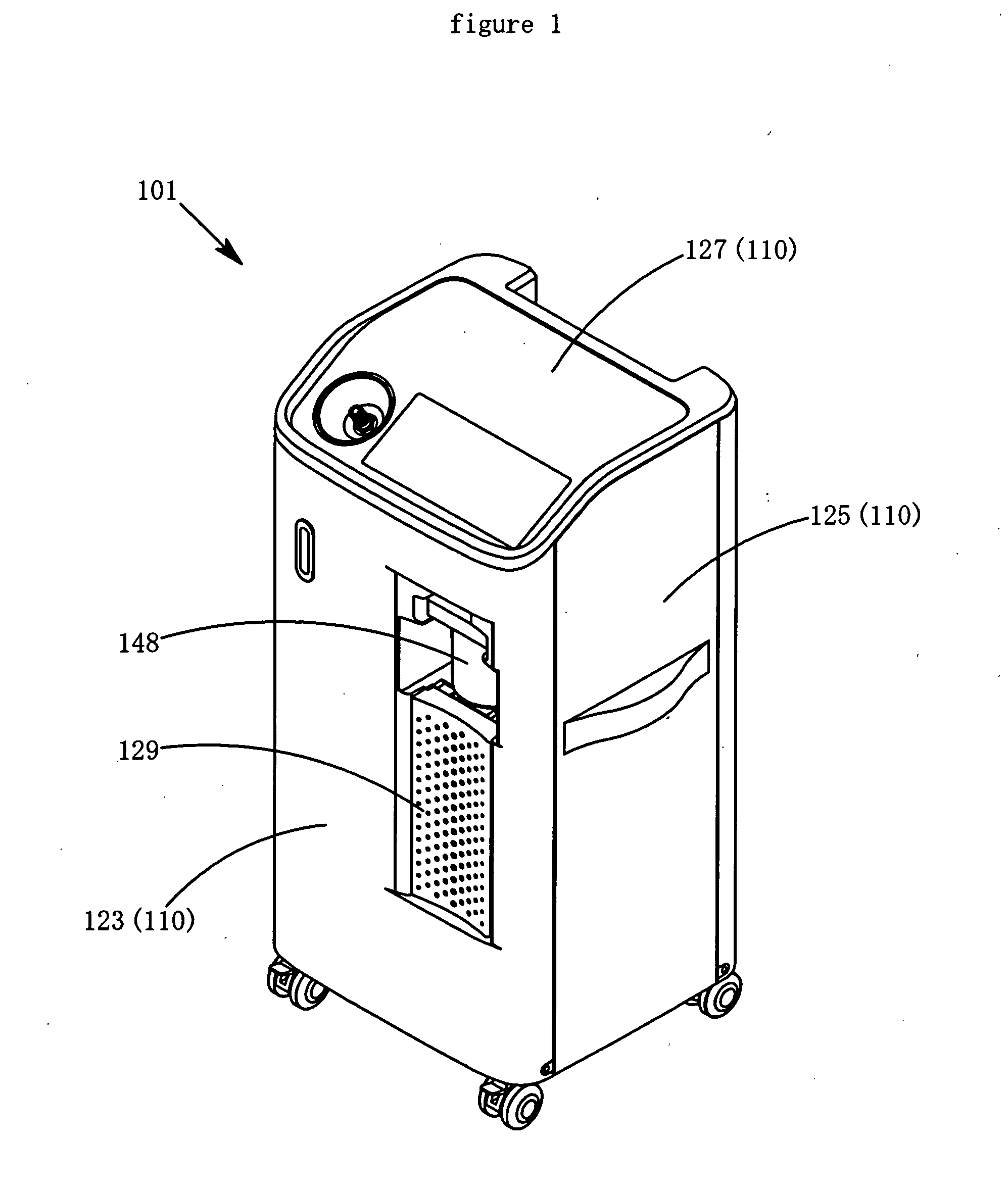
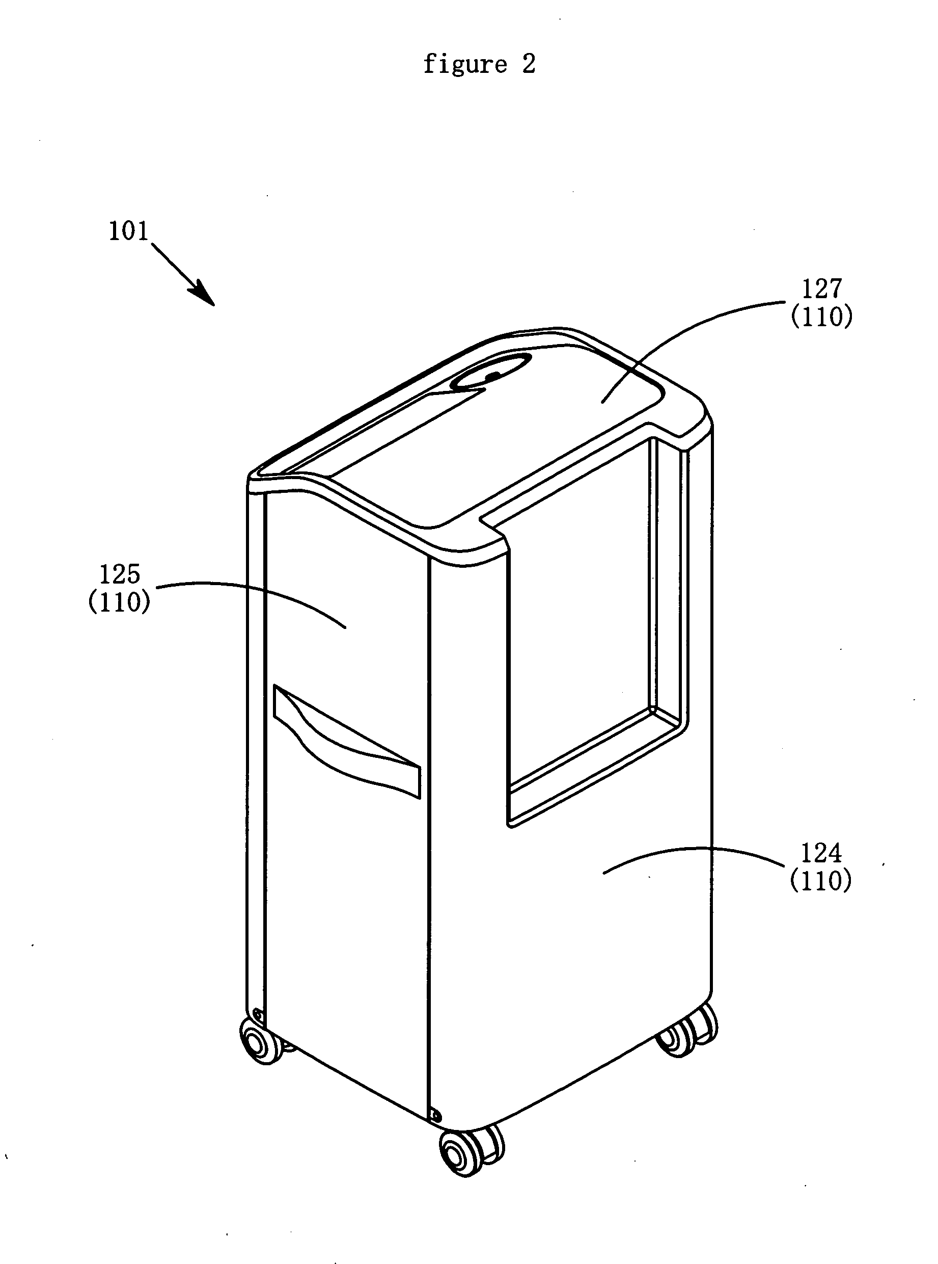
[0164]First, the oxygen concentrating device of the first embodiment will be described. FIG. 1 is a perspective view illustrating a state of an oxygen concentrating device 101 of the first embodiment of the present invention seen from the front side. FIG. 2 is a perspective view illustrating a state of the oxygen concentrating device 101 of the first embodiment of the present invention seen from the back side. FIG. 3 is a perspective view illustrating a state in which a front cover 123, a back cover 124, and an upper cover 127 are detached from the oxygen concentrating device 101 of the first embodiment of the present invention and seen from the front side. FIG. 4 is a perspective view illustrating a state in which the front cover 123, the back cover 124, and the upper cover 127 are detached from the oxygen concentrating device 101 of the first embodiment of the present invention and seen from the back side. FIG. 5 is a perspe...

Example

[0194]2.0 Oxygen Concentrating Device of Second Embodiment

[0195]The oxygen concentrating device of the second embodiment will now be described. FIG. 11 is a view illustrating a system flow of the oxygen concentrating device of the second embodiment of the present invention. The oxygen concentrating device illustrated in FIG. 11 includes a plurality of components such as adsorbing columns 206, 207 storing an adsorbent capable of selectively adsorbing nitrogen contained in the material air; a storing tank 211 for temporarily storing the concentrated oxygen gas generated in the adsorbing columns 206, 207; a gas transferring means 203 for transferring the material air, the concentrated oxygen gas or exhaust gas; solenoid valves 204a, 240b, 205a, 205b for opening / closing a gas flow path connected to the adsorbing columns 206, 207; and a control means (not illustrated in FIG. 11) for controlling each part. In the oxygen concentrating device illustrated in FIG. 11, a compressor capable of ...


PUM


Abstract

An oxygen concentrating device easy to assemble and able to reduce production costs. The oxygen concentrating device (101) comprises a plurality of components including an adsorbing column (102) storing adsorbent capable of selectively adsorbing nitrogen contained in material air, a storing tank (103) for temporarily storing concentrated oxygen gas generated in the adsorbing column (102), a gas transferring means (104) for transferring material air, concentrated oxygen gas or exhaust gas, a solenoid valve (106) for opening/closing or switching a gas flow path connected to the adsorbing column (102), and a control means (108) for controlling the gas transferring means and/or the solenoid valve, resin supports (109) for positioning and supporting the plurality of components at predetermined locations, and a plurality of resin covers (110) covering the outer sides of the supports (109), the supports (109) being formed by injection molding.

Description

TECHNICAL FIELD[0001]The present invention relates to an oxygen concentrating device for generating a concentrated oxygen gas with increased oxygen concentration. In particular, it relates to a medical oxygen concentrating device for supplying concentrated oxygen gas to a patient with respiratory system illness such as lung emphysema and bronchitis.BACKGROUND ART[0002]An oxygen inhalation therapy is known as a method effective in treating respiratory system illness such as lung emphysema and bronchitis. The oxygen inhalation therapy alleviates pain and suffering that patients feel such as difficulty in breathing, by supplying oxygen to tissue cells lacking oxygen by making patients inhale the concentrated oxygen gas and maintaining the function of the tissue cells. In Japan, health insurance started to be applied even to oxygen inhalation therapy at home, and patients being treated with oxygen inhalation therapy at home increased from 1985. In view of such actual situation, the dema...

Claims


Application Information

Patent Timeline
IPC IPC(8): B03C1/0355
CPCA61M2205/42B01D53/0407B01D53/0454B01D53/053B01D2256/12B01D2257/102A61M16/101B01D2259/402B01D2259/4533B01D2259/455C01B13/0259C01B2210/0046B01D2259/40003A61M16/1055A61M16/107A61M2016/1025A61M16/10B01D53/04C01B13/02
Inventor SAKURAI, HIDEYUKIWATANABE, NOBORU
Owner SANYO ELECTRONICS IND CO LTD
Why Eureka
Try Eureka