Method for producing a head element for heaters

a head element and heater technology, applied in the direction of manufacturing tools, indirect heat exchangers, light and heating apparatus, etc., can solve the problems of increasing the number of working steps and production costs, difficult to make the flow of fusion material in the dies appropriate, and difficult to be treated by fusion, so as to reduce the time and cost of head element production

Inactive Publication Date: 2004-07-29
R P S MECCANICA SRL
View PDF12 Cites 1 Cited by
  • Summary
  • Abstract
  • Description
  • Claims
  • Application Information

AI Technical Summary

Benefits of technology

[0026] Another object of the present invention is to propose a method, which allows a reduction of time and costs of the head element production.
[0027] A further object of the present invention is to propose a method, which allows using ferrous material, which is cheap and easy to work.
[0028] A still further object of the present invention is to propose a head element obtained by the above mentioned method, whose production is cheap and does not require extensive time, and which is shapely, so as to reduce as much as possible other finishing operations.
[0029] In particular, the proposed head element is produced in such a way that it does not require grinding of extended surfaces, which have been welded in critical points.

Problems solved by technology

The drawbacks of the head elements obtained in this way derive from the difficulty in producing, by fusion, a head element which is hollow and features holes of small diameter conducting to the cavity.
This constructive feature imposes the use of cores, which must be crumbled in order to be removed from the piece obtained by fusion, thus increasing the number of working steps and production costs.
Moreover, it is difficult to make the fused material flow appropriately in the dies to avoid a high number of wastes.
This problem imposes also the choice of those materials which feature good flowability when fused, in place of other materials, which would be cheaper, but are more difficult to be treated by fusion.
Nevertheless, the welding of the two semi-shells is very difficult, because of the welding length and critical position, as it extends along the matching line of the two curved surfaces and must pass across further curved sections.
Since the head element must be liquid-tight, so the welding must be performed correctly, thus increasing the difficulty and costs of this working operation.
This step increases again the production time and costs.

Method used


Image

  • Method for producing a head element for heaters
  • Method for producing a head element for heaters
  • Method for producing a head element for heaters

Examples


first embodiment

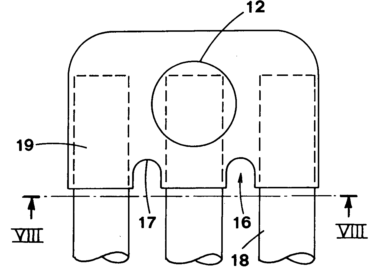
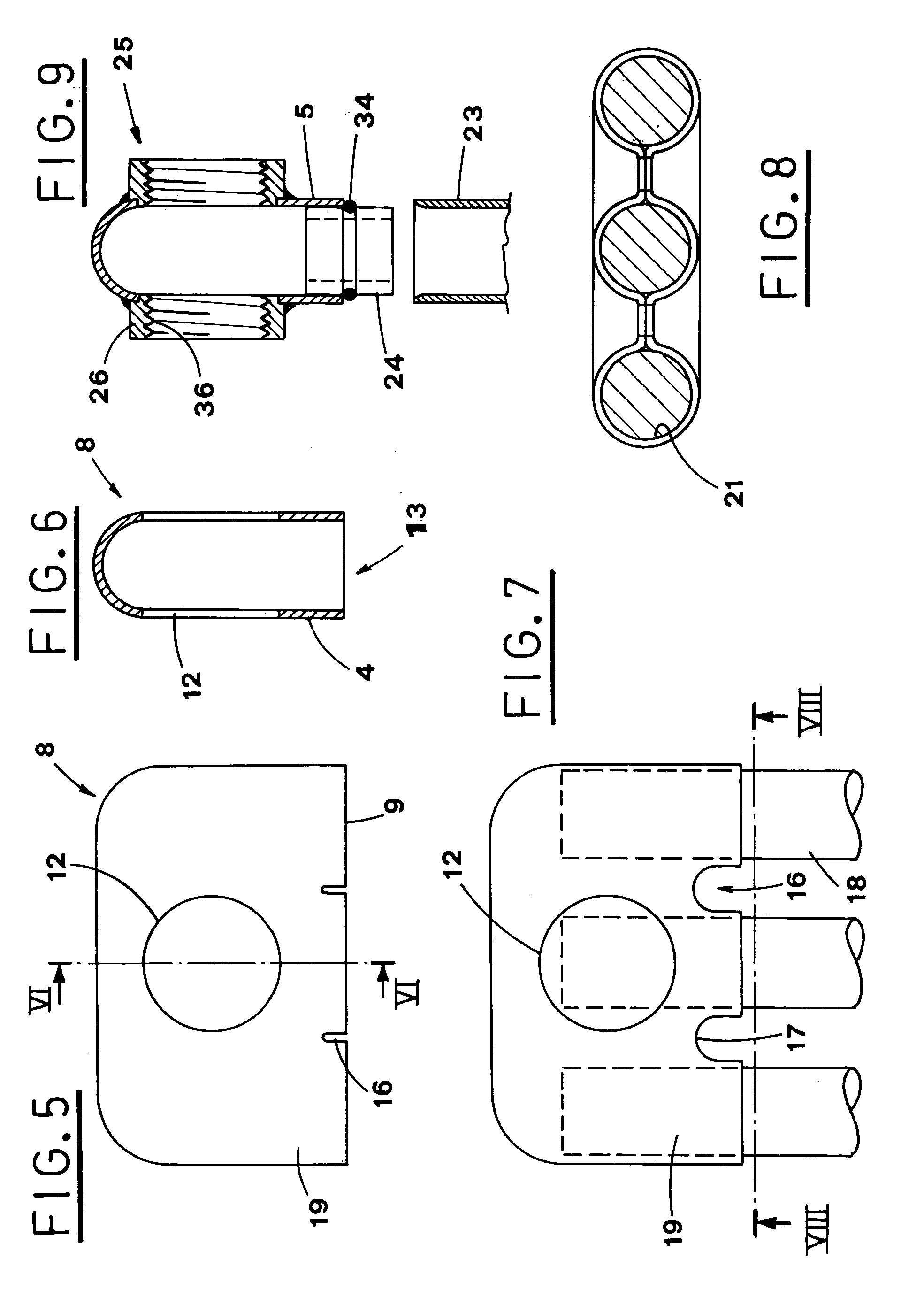
[0080] shown in FIG. 9, the fastening means 25 on each lateral through aperture 12 are obtained by welding a threaded ring 26 around the lateral through aperture 12.

[0081] A threaded joint (not shown) is then screwed into the inner threading 36 of the ring 26 during the heater assembly.

[0082] According to another embodiment of the fastening means 25, shown in Figures from 11 to 15, a circular crown 27, extending around each lateral through aperture 12, is obtained by applying a pressure directed outwards, thus deforming plastically the hollow body 8 and forming a protruding edge 31.

[0083] The protruding edge 31 is obtained by introducing a flat core 28 into the hollow body 8 through the open side 6, before the holes 13 are made (FIG. 11).

[0084] The flat core 28 is equipped with a floating element 29, which is situated in a position matching each lateral through aperture 12 and is pushed outwards alternately in opposite directions, thus forming the protruding edge 31 on the circular...

second embodiment

[0117] the fastening means 25 on each lateral through aperture 12 are obtained by a circular crown 27 surrounding the lateral through aperture 12, which has been plastically deformed by pressing outwards, so as to form a protruding edge 31.

[0118] A threaded ring 38 is introduced into the seat defined by the protruding edge 31 and fixed therein either by welding spot or by slight deformations made in the material of the head. Any other means can be used to fix the threaded ring and avoid rotation thereof.

[0119] Otherwise, the circular crown 27 is left free to be fastened to an adjacent head element by welding.

[0120] Consequently, the objects listed in the introduction have been obtained by the method for producing head elements and the head element described above.

[0121] The head element is produced in a single body, by more pressing steps, without the drawbacks resulting from the fusion procedure and without the necessity to weld two semi-shells to each other, or other elements of ...


PUM

PropertyMeasurementUnit
areaaaaaaaaaaa
circumferenceaaaaaaaaaa
diameteraaaaaaaaaa

Abstract

According to a method for producing head elements for heaters, a piece of sheet metal (1) is deep drawn and cut along the edge (9) of an open side (6) to obtain a hollow body (8) with larger and narrower sides (4,5,14,15). An aperture (12) is made on each opposite larger side (4,5) of the hollow body, and threaded rings (26) are then applied around the lateral through apertures (12). Notches (16) are made on the opposite large sides (4,5), along the edge (9) of the open side (6), and then three cores (18) are introduced through the edge (9), so that a flange (17) around the notches (16) can be made by pressing, so as to close the sheet metal (1) around the cores (18) widening the notches (16). After the cores (18) have been removed, the edge (9) is welded along the flange (17) of the widened notches (16), thus obtaining holes (21) separated from each other.

Description

[0001] The present invention relates to the production of heaters.[0002] In particular, the present invention relates to the production of head elements used for supporting and connecting the tubular heating elements, which form the heater.DESCRIPTION OF THE PRIOR ART[0003] According to known methods, heaters for e.g. civil and industrial use are produced by joining tubular elements using head elements, which support and join the tubular elements with each other.[0004] The groups, composed of two or more tubular elements joined one to another by head elements, are connected to each other by liquid-tight connection applied between each pair of head elements, thus forming a heater.[0005] There are different methods for producing the head elements.[0006] The Patent Publication FR 1.201.614 describes the preparation of the head element by fusion technique and subsequent working of the so obtained workpiece.[0007] The obtained head element is composed of a hollow body with four parallel ...

Claims


Application Information

Patent Timeline
Patent Type & Authority Applications(United States)
IPC IPC(8): B21D53/04F28F9/02F28D1/053F28D7/16F28F9/26F28F21/08
CPCF28D1/05308F28F9/262Y10T29/49389F28F9/0221F28F21/088F28F21/08
Inventor LOLLI, WALTER
Owner R P S MECCANICA SRL
Why Eureka
Try Eureka