Method of controlling a landing guide path of an aircraft

a technology of landing guide path and aircraft, which is applied in the direction of air braking surface, air flow influencer, drag reduction, etc., can solve the problems of increasing the power of the aircraft, reducing the capacity of the aircraft, and high utilization of air traffic capacity of many airports

Inactive Publication Date: 2004-08-12
AIRBUS OPERATIONS GMBH
View PDF8 Cites 29 Cited by
  • Summary
  • Abstract
  • Description
  • Claims
  • Application Information

AI Technical Summary

Benefits of technology

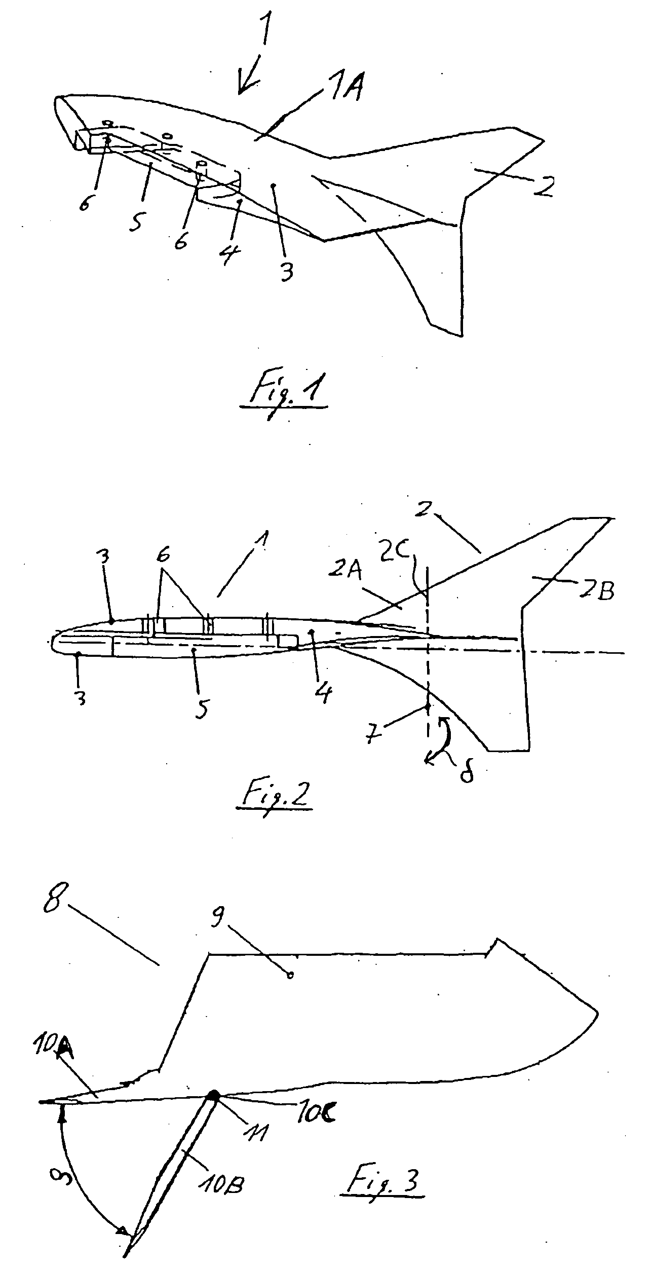
[0008] The above objects have been achieved according to the invention in a device for controlling the landing approach of an aircraft, including a respective pivotable control element arranged respectively at the outboard wingtip of each wing of the aircraft. These pivotable control elements can be selectively pivoted to deflected positions, whereby the coefficient of lift of the aircraft is not influenced (i.e. remains essentially constant with no practically significant change), the coefficient of drag of the aircraft is altered, and the aerodynamic drag or flow resistance of the aircraft is increased. As a result, the glide path angle is made steeper, i.e. increased relative to the horizontal plane. Preferably, each pivotable control element is pivotally connected to a fixed plane or surface member, which in turn is rigidly connected to or a part of an aerodynamic component that is secured to the respective wingtip. The aerodynamic component may, for example, be embodied as a wingtip fence or a winglet, which is additionally provided with the pivotable control element. The pivot axis preferably extends perpendicularly to the major plane of the wing or parallel to the yaw axis of the aircraft.
[0009] The above objects have further been achieved according to the invention in a method of operating the inventive device, whereby the respective pivotable control elements on the wingtips of the two wings of the aircraft are pivotally deflected, mirror symmetrically in unison, so as to increase the total coefficient of drag, without exerting a net yaw influence on the aircraft and without influencing the total coefficient of lift. Thus, the pivotal deflection of the inventive control elements simply introduces an increased drag to the overall aerodynamic configuration of the aircraft, which thereby achieves a faster descent along a steeper glide path in a simply and finely controllable manner. Particularly, the pivotal deflection of the inventive control elements achieves a fine adjustment that is superimposed on the basic aerodynamic configuration of the aircraft that is set by the control adjustments of the general control surfaces or control elements such as the flaps, spoilers, engine thrust adjustment, etc. Furthermore, by carrying out rapid fluctuating deflections with a time varying deflection angle or magnitude of the pivotable control elements, a rapid collapse of the wingtip vortices can be achieved.
[0010] By making the gliding descent of the aircraft steeper and faster over a shorter horizontal distance along the glide path, the invention reduces the total time required for a landing process, and thereby increases the take-off and landing cycle time and throughput capacity of the airport. Moreover, the invention makes it possible to carry out a finely adjustable drag control of the aircraft with a large bandwidth or large range of control, while being essentially independent of the lift and other moments of the aircraft. The inventive control further makes it possible to reduce the flight noise of the aircraft, especially in the landing configuration.
[0012] The aerodynamic effect of the inventive control elements can be determined by model tests and measurements in a wind tunnel, whereby the determined test data can be used as the basis for integrating the inventive control elements into the overall flight control system of the aircraft. In other words, by providing the appropriate data that associates the control element deflection with the resulting aerodynamic effect thereof, the pivoting deflection of the inventive control elements can be readily controlled from the general flight control system of the aircraft, e.g. including a flight control computer. It is further advantageous, that the movable control elements can be controlled in a symmetrical and synchronized manner to achieve the above described glide path control without any yaw effect, but alternatively can be deflected independently and / or asymmetrically on the two sides of the aircraft so as to achieve a yaw control. This effect is especially advantageous in emergency situations such as an emergency descent of the aircraft and / or in the event of an engine failure, to support and supplement the other conventional control devices for maintaining the yaw control of the aircraft.
[0013] Appropriate actuation of the inventive pivotable control elements contributes to a rapid collapse of the trailing vortices of the wingtips of the aircraft. This is especially advantageous because then a shorter spacing (in time and distance) may be maintained between a respective aircraft taking off or landing and the next successive aircraft that can take-off or land, in view of the rapid collapse of the trailing vortices of the preceding aircraft. Thereby, a further increase of the take-off and landing rate can be achieved.

Problems solved by technology

A sharp increase in air traffic in recent years has led to a high utilization and partially an overloading of the air traffic capacity of many airports.
Without expanding the physical runway facilities and the like of existing airports, or building new airports, a further increase in capacity can only be achieved by reducing the time required for the take-off and landing of each aircraft.
Reducing the time required for the take-off of an aircraft basically requires an increase in the power of the aircraft, and is thus complicated and costly.
Unfortunately, these conventional control elements can only achieve a variation of the lift and of the aerodynamic drag in a mutually coupled manner.
The resulting compound effects of any control adjustment are thus rather complex, and consequently require rather complex systems for controlling the adjustments of the control elements, and substantially limit the possibility of any further reductions in the time or distance required for the landing approach of the aircraft.
Appropriate actuation of the inventive pivotable control elements contributes to a rapid collapse of the trailing vortices of the wingtips of the aircraft.

Method used


Image

  • Method of controlling a landing guide path of an aircraft
  • Method of controlling a landing guide path of an aircraft
  • Method of controlling a landing guide path of an aircraft

Examples


Embodiment Construction

[0019] As shown in FIG. 1, an aerodynamic component 1 according to the invention is generally surfacially extending and aerodynamically contoured and is adapted to be connected to each respective outboard wingtip of a wing 17 of an aircraft 15, as generally shown in FIG. 4. The aerodynamic component 1 includes a main plane body 1A that is rigid and adapted to be fixed to the wingtip of the aircraft wing 17 with the main plane body 1A extending aerodynamically smoothly and continuously from the wingtip of the aircraft wing 17 and along the major plane of the wing 17 (e.g. the plane extending along both the leading edge and the trailing edge of the wing 17).

[0020] The aerodynamic component 1 further comprises a control surface member 2 that also has a generally surfacially extending or planar and aerodynamically contoured configuration. The control surface member 2 is connected and smoothly transitions to the main plane body 1A. Preferably, the plane of the control surface member 2 st...


PUM


Abstract

A method of controlling a landing guide path of an aircraft and a method of steeping a landing guide path of an aircraft include rotating a portion of an aerodynamic component to increase a drag without influencing a lift. A method of controlling a landing guide path of an aircraft including an aerodynamic component having a main portion and a control portion, the main portion connected to a wing of the aircraft, and the control portion including a fixed member connected to a pivotable member. The method includes rotating the pivotable member to increase a drag without influencing a lift.

Description

[0001] This application claims priority under 35 U.S.C. .sctn.119 to German Patent Application 101 60 315.0, filed on Dec. 7, 2001, and under 35 U.S.C. .sctn.120 to U.S. patent application Ser. No. 10 / 313,052, filed on Dec. 6, 2002, the disclosures of which are incorporated by reference herein in their entirety.[0002] 1. FIELD OF THE INVENTION[0003] The invention relates to an arrangement of control elements and an associated method for controlling the landing approach of an aircraft by a controlled descent along a glide path.[0004] 2. DISCUSSION OF THE RELATED ART[0005] A sharp increase in air traffic in recent years has led to a high utilization and partially an overloading of the air traffic capacity of many airports. Without expanding the physical runway facilities and the like of existing airports, or building new airports, a further increase in capacity can only be achieved by reducing the time required for the take-off and landing of each aircraft. Reducing the time required ...

Claims


Application Information

Patent Timeline
Patent Type & Authority Applications(United States)
IPC IPC(8): B64C9/32
CPCB64C9/32B64C23/065Y02T50/164B64C9/323B64C23/076Y02T50/10
Inventor WYREMBEK, SUSANNEMAY, PETERMUTHREICH, KLAUS
Owner AIRBUS OPERATIONS GMBH
Why Eureka
Try Eureka