Method and device for steepening a landing approach of an aircraft

a landing approach and aircraft technology, applied in emergency apparatus, transportation and packaging, air-flow influencers, etc., can solve the problems of increasing the power of the aircraft, reducing the capacity of the aircraft, and affecting the capacity of the air traffic of many airports

Active Publication Date: 2003-06-12
AIRBUS OPERATIONS GMBH
View PDF7 Cites 39 Cited by
  • Summary
  • Abstract
  • Description
  • Claims
  • Application Information

AI Technical Summary

Problems solved by technology

A sharp increase in air traffic in recent years has led to a high utilization and partially an overloading of the air traffic capacity of many airports.
Without expanding the physical runway facilities and the like of existing airports, or building new airports, a further increase in capacity can only be achieved by reducing the time required for the take-off and landing of each aircraft.
Reducing the time required for the take-off of an aircraft basically requires an increase in the power of the aircraft, and is thus complicated and costly.
Unfortunately, these conventional control e

Method used


Image

  • Method and device for steepening a landing approach of an aircraft
  • Method and device for steepening a landing approach of an aircraft
  • Method and device for steepening a landing approach of an aircraft

Examples


Embodiment Construction

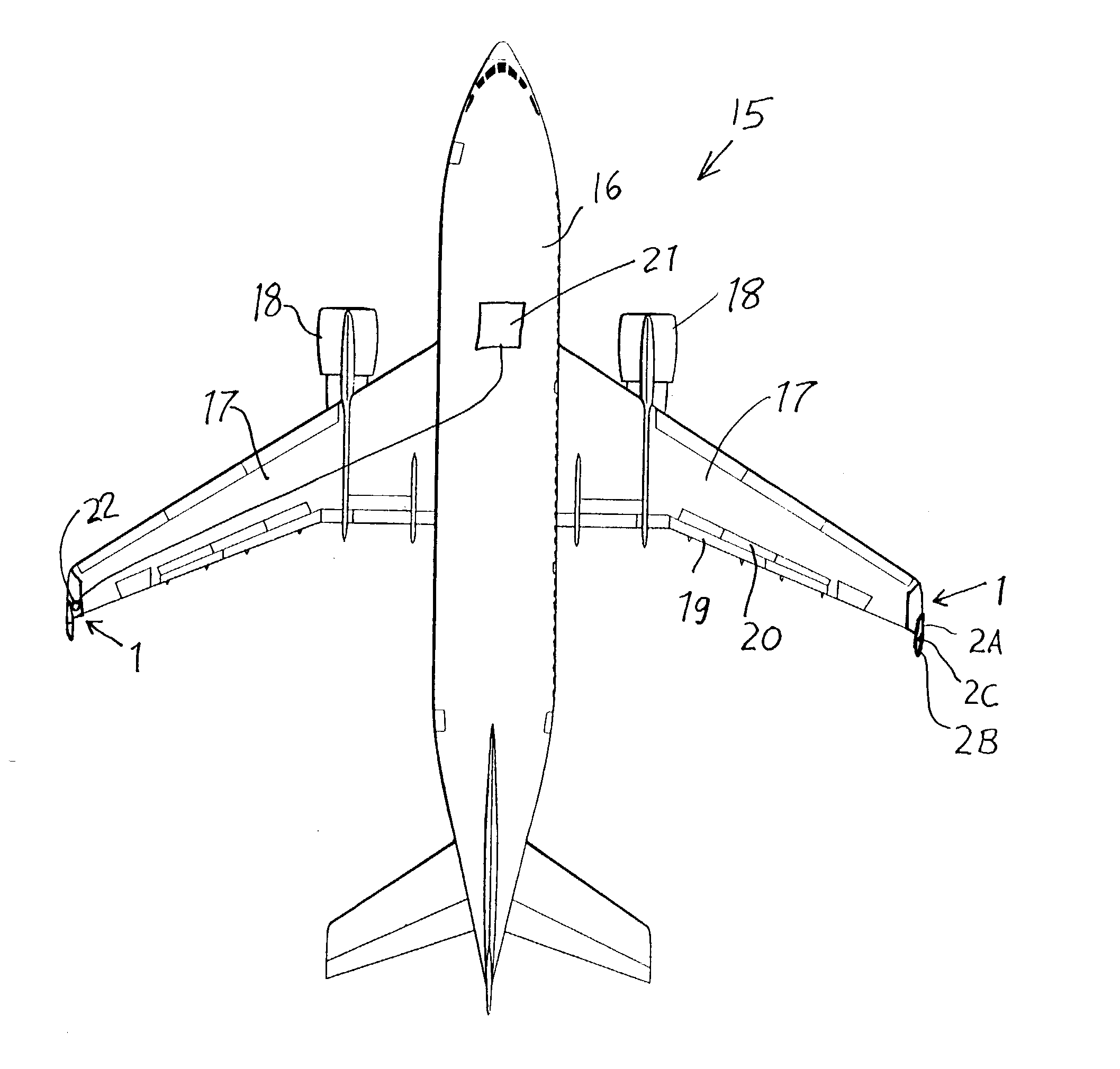
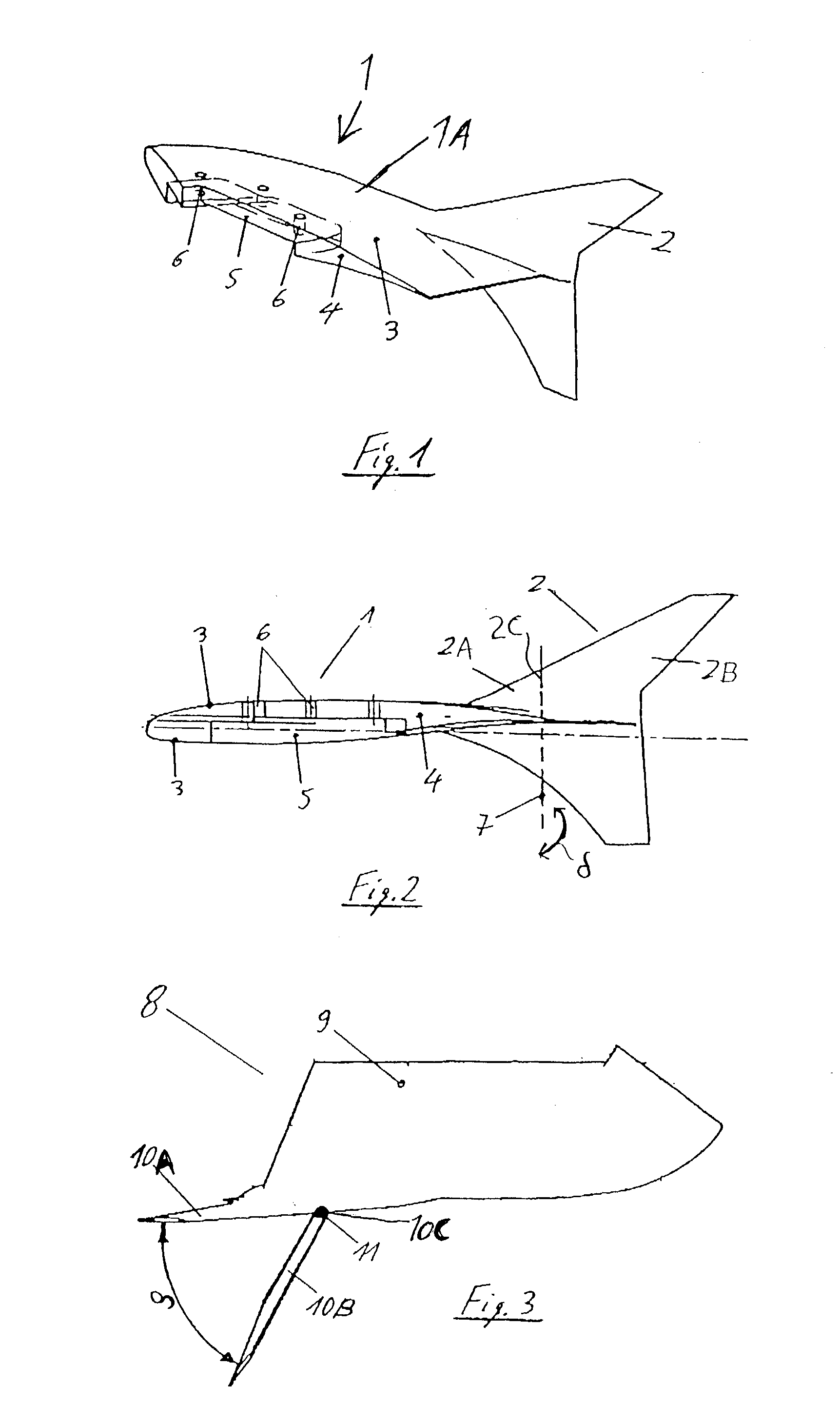
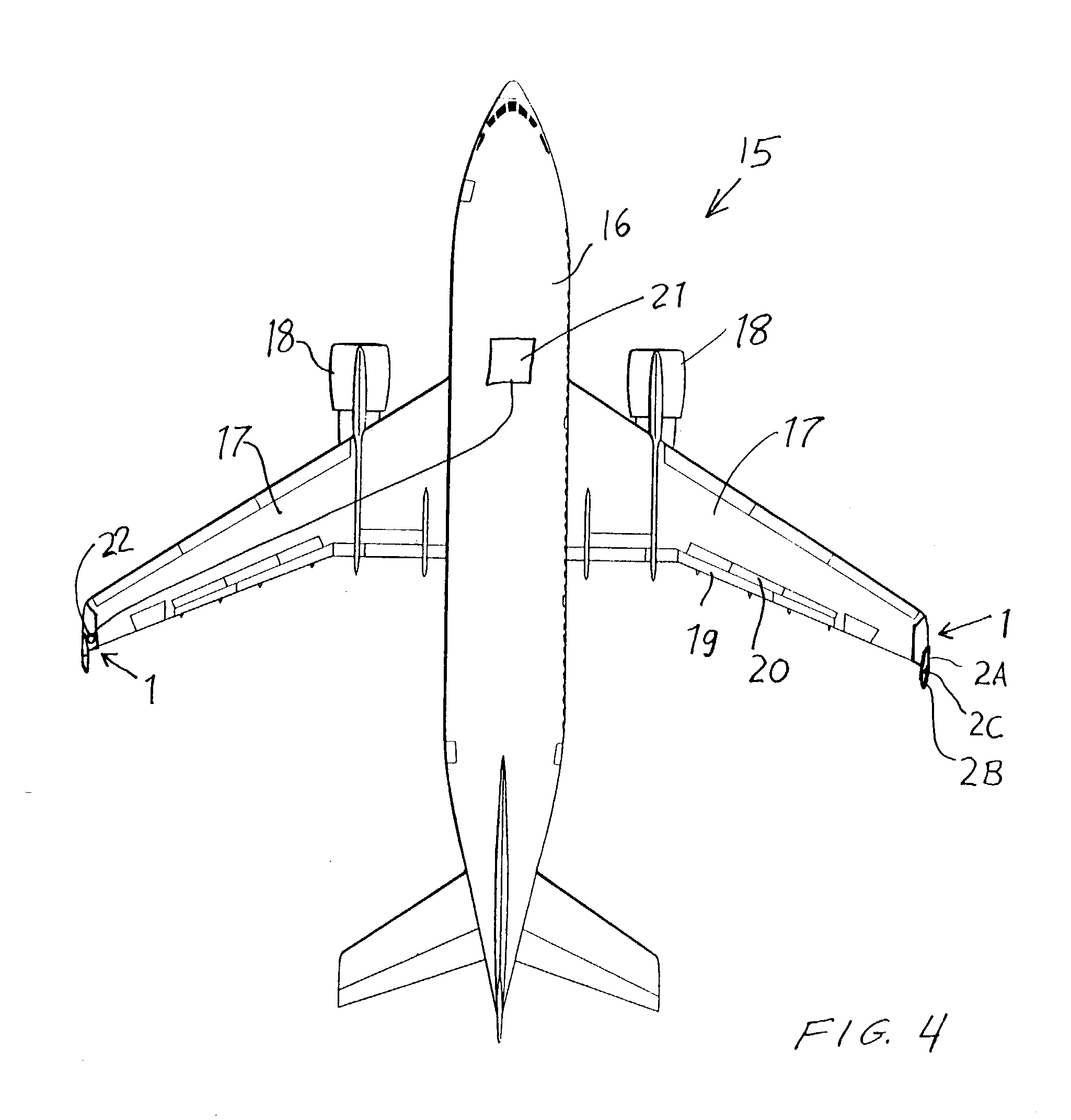
[0017] As shown in FIG. 1, an aerodynamic component 1 according to the invention is generally surfacially extending and aerodynamically contoured and is adapted to be connected to each respective outboard wingtip of a wing 17 of an aircraft 15, as generally shown in FIG. 4. The aerodynamic component 1 includes a main plane body 1A that is rigid and adapted to be fixed to the wingtip of the aircraft wing 17 with the main plane body 1A extending aerodynamically smoothly and continuously from the wingtip of the aircraft wing 17 and along the major plane of the wing 17 (e.g. the plane extending along both the leading edge and the trailing edge of the wing 17).

[0018] The aerodynamic component 1 further comprises a control surface member 2 that also has a generally surfacially extending or planar and aerodynamically contoured configuration. The control surface member 2 is connected and smoothly transitions to the main plane body 1A. Preferably, the plane of the control surface member 2 st...


PUM


Abstract

To control and particularly steepen the landing glide path of an aircraft, a respective aerodynamic component mounted on each wingtip includes a fixed plane member and a pivotable control element pivotally connected to the fixed plane member. The pivot axis is perpendicular to the major plane of the wing. The pivotable control element can be selectively pivotally deflected about the pivot axis relative to the fixed plane member, so as to thereby increase the overall drag without influencing the overall lift of the aircraft. This achieves a fine adjustment that is superimposed on the basic landing configuration established by the setting of the flaps, spoilers, engine thrust, etc. By increasing the drag without influencing the lift, this steepens the landing glide path slope.

Description

PRIORITY CLAIM[0001] This application is based on and claims the priority under 35 U.S.C. .sctn.119 of German Patent Application 101 60 315.0, filed on Dec. 7, 2001, the entire disclosure of which is incorporated herein by reference.[0002] The invention relates to an arrangement of control elements and an associated method for controlling the landing approach of an aircraft by a controlled descent along a glide path.BACKGROUND INFORMATION[0003] A sharp increase in air traffic in recent years has led to a high utilization and partially an overloading of the air traffic capacity of many airports. Without expanding the physical runway facilities and the like of existing airports, or building new airports, a further increase in capacity can only be achieved by reducing the time required for the take-off and landing of each aircraft. Reducing the time required for the take-off of an aircraft basically requires an increase in the power of the aircraft, and is thus complicated and costly. ...

Claims


Application Information

Patent Timeline
IPC IPC(8): B64C9/32
CPCB64C9/32B64C23/065Y02T50/164B64C9/323B64C23/076Y02T50/10
Inventor WYREMBEK, SUSANNEMAY, PETERMUTHREICH, KLAUS
Owner AIRBUS OPERATIONS GMBH
Why Eureka
Try Eureka