

Manufacturing method of fuel tank welding joint
a welding joint and fuel tank technology, applied in the direction of manufacturing tools, functional valve types, machines/engines, etc., can solve problems such as heat loss
Active Publication Date: 2004-08-26
TOYODA GOSEI CO LTD
View PDF15 Cites 8 Cited by
- Summary
- Abstract
- Description
- Claims
- Application Information
AI Technical Summary
Benefits of technology
The present invention provides a fuel tank welding joint that minimizes the release of fuel vapor into the atmosphere. The joint includes a joint main body made of a first resin material that is weldable to a fuel tank and a barrier layer made of a second resin material that is more fuel-impermeable than the first resin material. The barrier layer is formed on the surface of the joint main body and is integrally formed with the joint main body to prevent fuel vapor from leaking. The joint is thermally welded at the welded edge portion of the joint main body on the fuel tank, and the barrier layer is adhesive and chemically reactive with the first resin material, further preventing fuel vapor from being released. The joint is designed to minimize environmental safety concerns and improve the adhesive strength at the end face where it is joined to the barrier layer.
Problems solved by technology
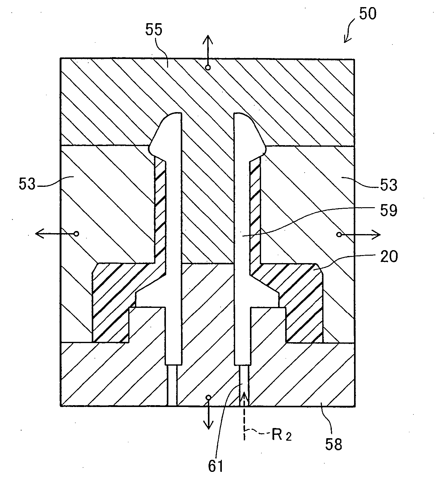
The second resin material flows through the narrow end of the tube portion during the injection molding of the barrier layer, resulting in shearing heat.
Method used
View moreImage
Smart ImageViewing Examples

Examples
Embodiment Construction
has been provided for the purpose of explaining the principles of the invention and its practical application, thereby enabling others skilled in the art to understand the invention for various embodiments and with various modifications as are suited to the particular use contemplated. The foregoing detailed description is not intended to be exhaustive or to limit the invention to the precise embodiments disclosed. Modifications and equivalents will be apparent to practitioners skilled in this art and are encompassed within the spirit and scope of the appended claims.
Login to View More PUM
| Property | Measurement | Unit |
|---|---|---|
| diameter | aaaaa | aaaaa |
| polar | aaaaa | aaaaa |
| clamping pressure | aaaaa | aaaaa |
Abstract
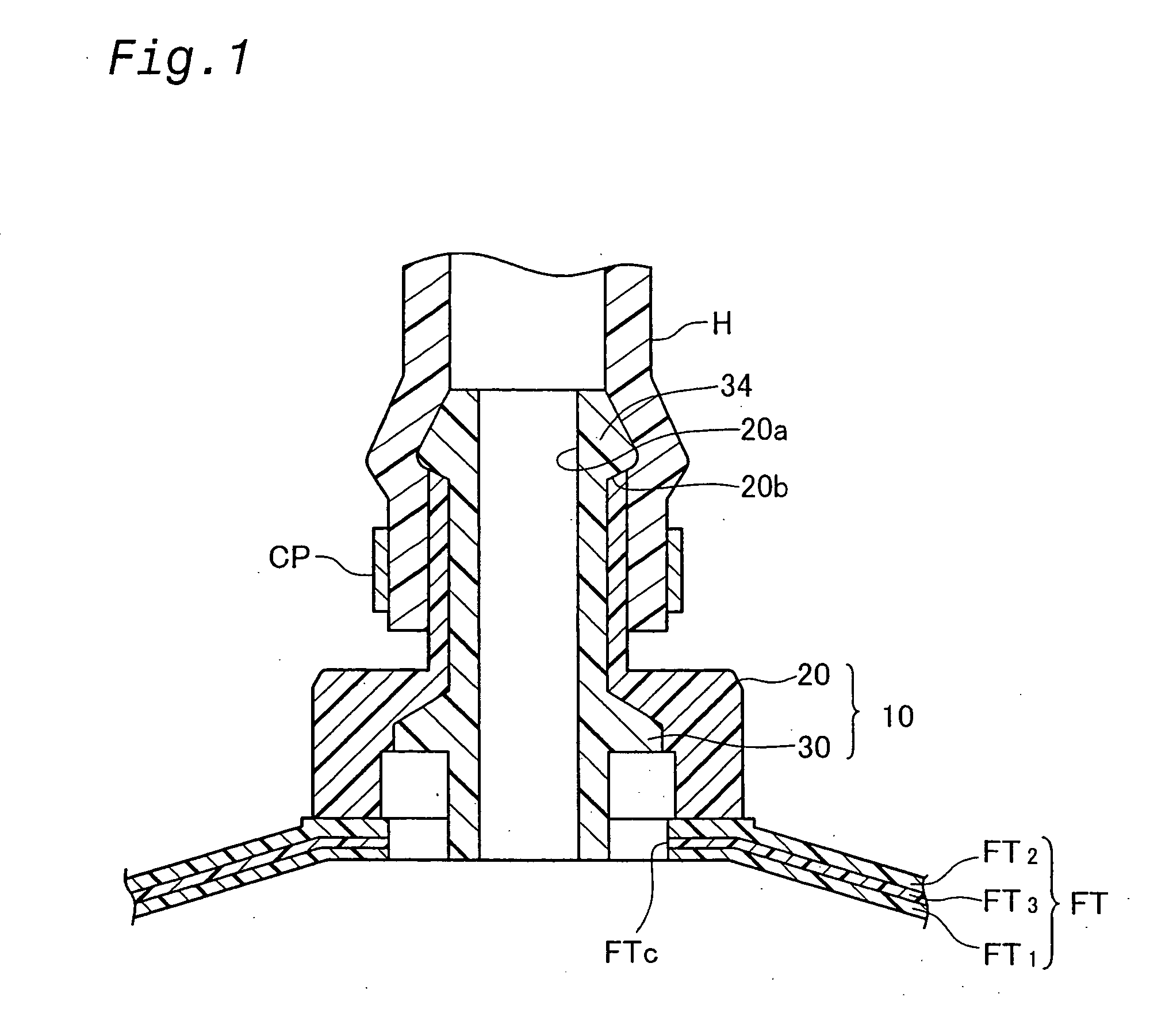
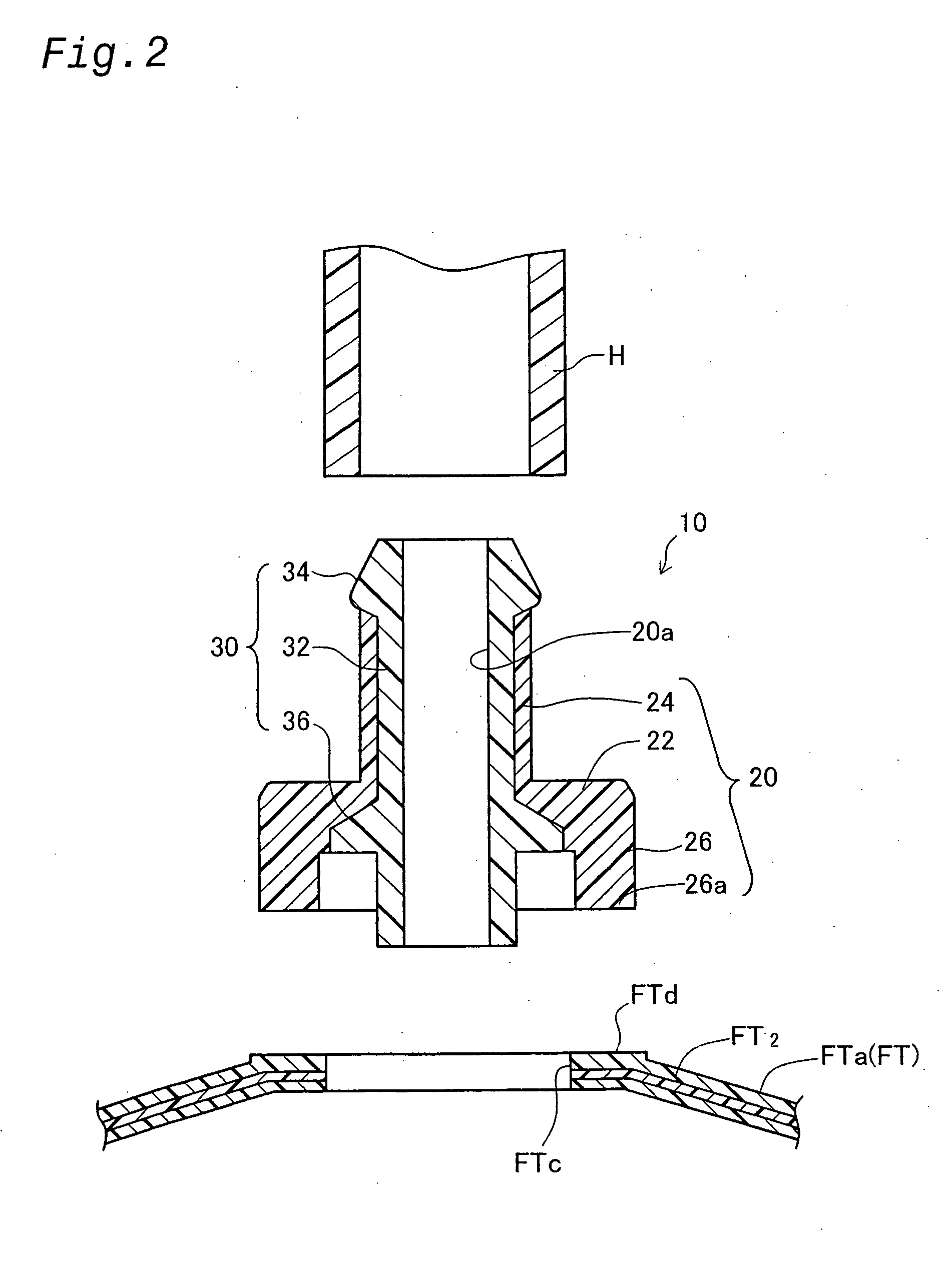
A welding joint 10 for a fuel tank reduces the amount of fuel vapor in the fuel tank that escapes into the atmosphere. The fuel tank welding joint 10 a joint main body 20 and a barrier layer laminated on the surface of the joint main body 20. The joint main body 20 is formed of a first resin material weldable to the wall of the fuel tank FT, and the barrier layer 30 is formed of a second resin material that is adhesively and chemically reactive with the first resin material and that is more fuel-impermeable than the first resin material. An end portion 34 formed so as to be exposed to the outside at the end of a tube portion 24 is formed on the barrier layer 30. When the barrier layer 30 is injection molded on the surface of the joint main body 20, the end portion 34 is formed by the flow of the second resin material through the end of the tube portion 24 to increase the adhesive strength of the end face where the parts are joined.
Description
[0001] This application claims the benefit of and priority from Japanese Application No. 2001-56806 filed Mar. 1, 20001, the content of which is incorporated herein by reference.[0002] 1. Field of the Invention[0003] The present invention relates to a welding joint for fuel tanks, which is welded to a tank wall of a fuel tank to provide a connecting passage between the interior of the fuel tank and the outside.[0004] 2. Description of the Related Art[0005] A example of a conventional fuel cut-off valve as a fuel tank welding joint is disclosed in JP 2000-8981A. FIG. 13 is a cross sectional view of a fuel cut-off valve 100. In FIG. 13, the fuel cut-off valve 100 comprises a case main body 102 welded to a tank upper wall FTa, a float 112, a spring 114, and a bottom plate 116. A connecting passage 102a is opened and closed by the float 112 according to a level of the fuel in the fuel tank FT. The upper part of the case main body 102 serves as a lid 104, which is welded to the tank top ...
Claims
Login to View More Application Information
Patent Timeline
 Patent Type & AuthorityApplications(United States)
IPC IPC(8): B29C45/16B60K15/077B60K15/03B60K15/035B65D6/40F02M37/00
CPCB29C45/16B29C2045/1687B60K15/03519B60K15/03177B29K2995/0067
InventorAOKI, TOMOHIDEKITO, HIROAKINISHI, HIROSHINAKAGAWA, MASAYUKI
OwnerTOYODA GOSEI CO LTD