Eureka AIR delivers breakthrough ideas for toughest innovation challenges, trusted by R&D personnel around the world.

Fuel tank welding joint and manufacturing method thereof

a technology for welding joints and fuel tanks, applied in the direction of liquid fuel feeders, machines/engines, transportation items, etc., can solve problems such as heat shearing

Inactive Publication Date: 2002-09-05
TOYODA GOSEI CO LTD
View PDF3 Cites 41 Cited by
  • Summary
  • Abstract
  • Description
  • Claims
  • Application Information

AI Technical Summary

Benefits of technology

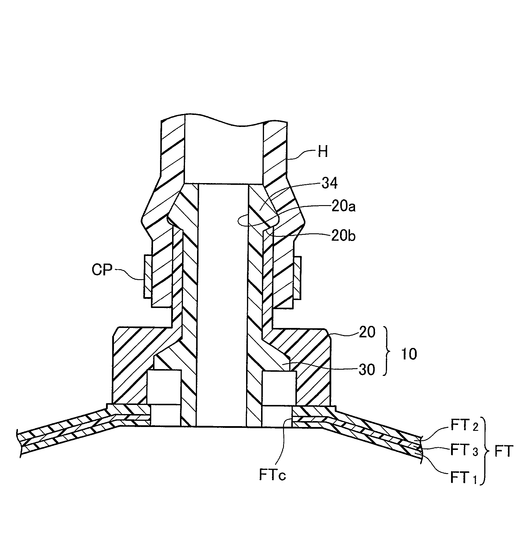
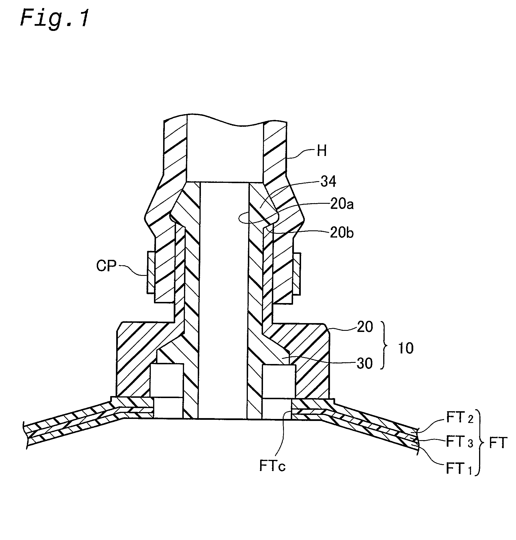
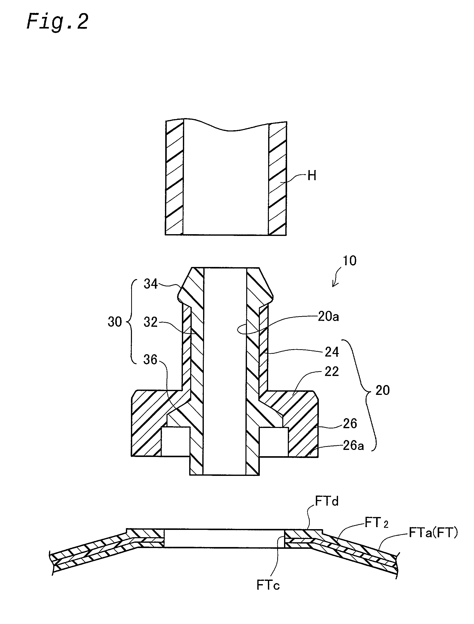
[0011] The fuel tank welding joint of the present invention is thermally welded at the welded edge portion of the joint main body on the wall of the fuel tank. The joint main body is formed of a first resin material that is weldable to the wall of the fuel tank, and is thus easily thermally welded to the welded edge portion. When the hose is connected to the tube portion of the joint main body, it is connected to the interior of the fuel tank through the connecting passage.
[0012] A barrier layer is also formed on the surface of the joint main body. The barrier layer is formed of a second resin material that has better fuel impermeability than the first resin material, thus shielding the joint main body from the outside and reducing fuel permeation.
[0013] Because the second resin material is also adhesively and chemically reactive with the first resin material, the barrier layer is integrally formed with the joint main body, leaving no gap between it and the joint main body, so as to further prevent fuel vapor in the fuel tank from being released.
[0014] The joint main body also has the following structure to improve the adhesive strength at the end face where it is joined to the barrier layer.
[0016] The second resin material flows through the narrow end of the tube portion during the injection molding of the barrier layer, resulting in shearing heat. The shearing heat keeps the second resin material at a high temperature to ensure better adhesion with the first resin material. The barrier layer is thus joined with considerable adhesive force to the end of the tube portion, with little danger of separation from the tube portion.
[0022] Because the burr cutting edge is directly subject to the clamping force between the first and second molds, dimensional imperfections resulting from resin contraction and the like during the manufacture of the joint main body are absorbed so as to prevent gaps from being created at the end of the cavity, thus ensuring that resins leaks will be prevented.

Problems solved by technology

The second resin material flows through the narrow end of the tube portion during the injection molding of the barrier layer, resulting in shearing heat.

Method used


Image

  • Fuel tank welding joint and manufacturing method thereof
  • Fuel tank welding joint and manufacturing method thereof
  • Fuel tank welding joint and manufacturing method thereof

Examples


Embodiment Construction

has been provided for the purpose of explaining the principles of the invention and its practical application, thereby enabling others skilled in the art to understand the invention for various embodiments and with various modifications as are suited to the particular use contemplated. The foregoing detailed description is not intended to be exhaustive or to limit the invention to the precise embodiments disclosed. Modifications and equivalents will be apparent to practitioners skilled in this art and are encompassed within the spirit and scope of the appended claims.


PUM

PropertyMeasurementUnit
diameteraaaaaaaaaa
polaraaaaaaaaaa
clamping pressureaaaaaaaaaa

Abstract

A welding joint 10 for a fuel tank reduces the amount of fuel vapor in the fuel tank that escapes into the atmosphere. The fuel tank welding joint 10 a joint main body 20 and a barrier layer laminated on the surface of the joint main body 20. The joint main body 20 is formed of a first resin material weldable to the wall of the fuel tank FT, and the barrier layer 30 is formed of a second resin material that is adhesively and chemically reactive with the first resin material and that is more fuel-impermeable than the first resin material. An end portion 34 formed so as to be exposed to the outside at the end of a tube portion 24 is formed on the barrier layer 30. When the barrier layer 30 is injection molded on the surface of the joint main body 20, the end portion 34 is formed by the flow of the second resin material through the end of the tube portion 24 to increase the adhesive strength of the end face where the parts are joined.

Description

[0001] This application claims the benefit of and priority from Japanese Application No. 2001-56806 filed Mar. 1, 20001, the content of which is incorporated herein by reference.[0002] 1. Field of the Invention[0003] The present invention relates to a welding joint for fuel tanks, which is welded to a tank wall of a fuel tank to provide a connecting passage between the interior of the fuel tank and the outside.[0004] 2. Description of the Related Art[0005] A example of a conventional fuel cut-off valve as a fuel tank welding joint is disclosed in JP 2000-8981A. FIG. 13 is a cross sectional view of a fuel cut-off valve 100. In FIG. 13, the fuel cut-off valve 100 comprises a case main body 102 welded to a tank upper wall FTa, a float 112, a spring 114, and a bottom plate 116. A connecting passage 102a is opened and closed by the float 112 according to a level of the fuel in the fuel tank FT. The upper part of the case main body 102 serves as a lid 104, which is welded to the tank top ...

Claims


Application Information

Patent Timeline
Patent Type & Authority Applications(United States)
IPC IPC(8): B29C45/16B60K15/03B60K15/077B60K15/035B65D6/40F02M37/00
CPCB29C45/16B29C2045/1687B29K2995/0067B60K15/03177B60K15/03519
Inventor AOKI, TOMOHIDEKITO, HIROAKINISHI, HIROSHINAKAGAWA, MASAYUKI
Owner TOYODA GOSEI CO LTD
Why Eureka
Eureka Blog
Learn More