Electrical junction box

Active Publication Date: 2004-10-28
ANDEN CO LTD 50
View PDF0 Cites 35 Cited by
  • Summary
  • Abstract
  • Description
  • Claims
  • Application Information

AI Technical Summary

Problems solved by technology

When water enters the case 51, there is a problem that failure is caused by the water wetting the relay part 52 and the like.
Thus, sometimes, it is impossible to easily determine whether or not the first bus bar is in a state of being completely fitted into the concave groove of the

Method used


Image

  • Electrical junction box
  • Electrical junction box
  • Electrical junction box

Examples


Example

[0051] With reference to the drawings, a first embodiment of the present invention will be described below.

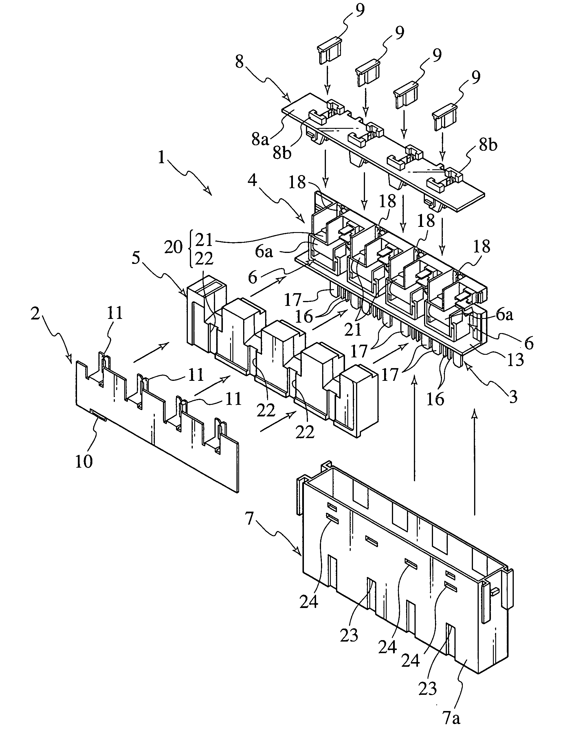
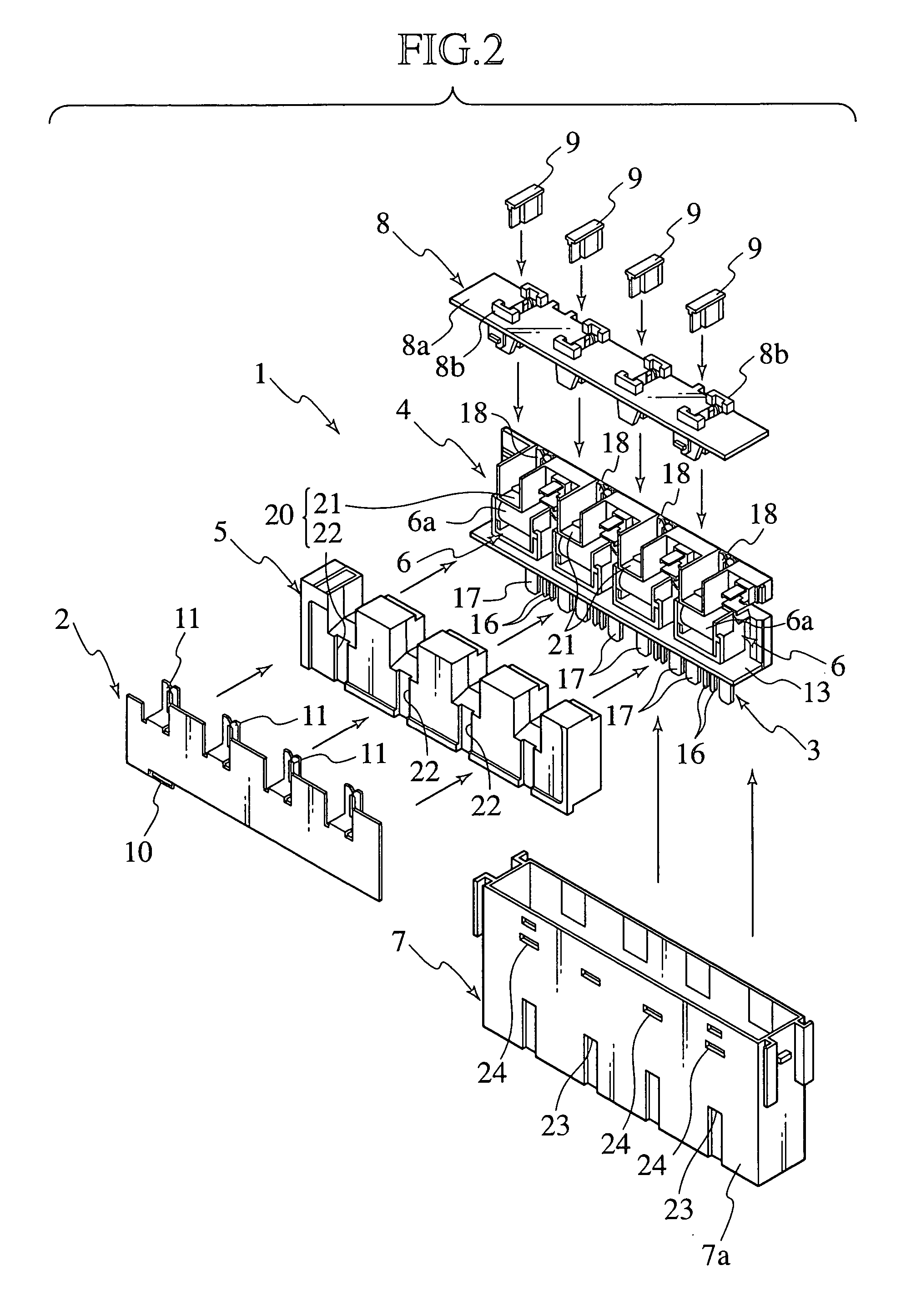
[0052] As shown in FIGS. 2 to 4, an electrical junction box 1 includes: a first bus bar 2; a bus bar attaching body 4 to which a second bus bar 3 is attached; an internal cover 5 which is attached to the bus bar attaching body 4 and covers relay parts 6; a case 7 which houses the first bus bar 2, the bus bar attaching body 4 and the internal cover 5; a fuse cavity 8 which is attached to an upper side of the case 7; and four fuses 9 which are mounted on fuse terminals 11 and 18 that are provided in the fuse cavity 8 in a protruding condition. Note that the arrow 30 in FIG. 4 shows a direction in which a water droplet W entering the case 7 through a fuse mounting part 8b is drained through a drainage channel in the electrical junction box 1.

[0053] The first bus bar 2 is manufactured by press-molding a rigid, conductive sheet metal having rigidity in a predetermined shape. A power...

Example

[0066] FIGS. 5 to 9 show how a bus bar positioning structure according to a second embodiment of the present invention is applied to a bus bar housed in an electrical junction box.

[0067] As shown in FIGS. 5 and 6, an electrical junction box 1 includes: a first bus bar 2; a bus bar attaching body 4 to which a second bus bar 3 is attached; an internal cover 5 which is attached to the bus bar attaching body 4 and covers relay parts 6; a case 7 which houses the first bus bar 2, the bus bar attaching body 4 and the internal cover 5; a fuse cavity 8 which is attached to an upper side of the case 7; and four fuses 9 which are mounted on fuse terminals 11 and 18 that are arrayed in predetermined positions in a fuse cavity 8.

[0068] A first bus bar 2 is manufactured by press-molding a rigid, conductive sheet metal in a predetermined shape. A power terminal 10 is formed at a lower end of the first bus bar 2, and a fuse terminal 11 is formed in each of the four spots of an upper end thereof.

[00...

Example

[0081] Next, with reference to FIGS. 10 and 11, an electrical junction box according to a third embodiment of the present invention will be described.

[0082] As shown in FIG. 10, an electrical junction box 1 includes: a first bus bar 2; a bus bar attaching body 4 to which a second bus bar 3 is attached; an internal cover 5 which is attached to the bus bar attaching body 4 and covers relay parts 6; a case 7 which houses the first bus bar 2, the bus bar attaching body 4 and the internal cover 5; a fuse cavity 8 which is attached to an upper side of the case 7; and four fuses 9 which are mounted on fuse terminals provided in the fuse cavity 8 in a protruding condition.

[0083] The first bus bar 2 is manufactured by press-molding a rigid, conductive sheet metal in a predetermined shape. A power terminal 10 is formed at a lower end of the first bus bar 2, and a fuse terminal 11 is formed in each of the four spots of an upper end thereof.

[0084] A bus bar attaching body 4 is manufactured in t...


PUM


Abstract

A relay part is housed in a case, a fuse mounting part is provided above the relay part in the case and a fuse is attached/detached to/from the fuse mounting part from above the case. In the case, provided are an internal cover and a bus bar supporting resin body, which cover the periphery of the relay part. A drainage channel is provided in outer surfaces of the internal cover and the bus bar supporting resin body. In addition, a drainage hole which drains water flowing through the drainage channel to the outside of the case is provided in the case. The drainage channel includes an upper groove which is formed in an upper surface of the bus bar supporting resin body and has an inclined surface on its bottom and a side groove which is communicated with a lowest portion of the inclined surface of the upper groove and is formed on a side of the internal cover.

Description

[0001] 1. Field of the Invention[0002] The present invention relates to an electrical junction box which houses fuses and relay parts in a case thereof.[0003] 2. Description of the Related Art[0004] As a conventional electrical junction box of this kind, one is disclosed in DE Patent Application Laid-Open No. 3209915. As shown in FIG. 1, in this electrical junction box 50, a relay part 52 is housed in a case 51. In the case 51, a fuse mounting part 53 is provided above the relay part 51. A fuse 54 is freely attached / detached to / from the fuse mounting part 53 from above the case 51.[0005] The electrical junction box 50 described above has an advantage that a state of the fuse 54 can be inspected, and the fuse 54 can be replaced, from above the case 51.[0006] However, in the conventional electrical junction box 50, the fuse mounting part 53 is disposed in a state of being exposed to an upper surface of the case 51. It is unavoidable that a water droplet or the like resulting from dew ...

Claims


Application Information

Patent Timeline
IPC IPC(8): H01H9/10H01H11/00H01H85/00H01H85/20H01R13/52H01R13/68H01R25/16
CPCH01H9/10H01H11/0056H01H85/0026H01H85/205H01H2085/208H01R13/5227H01R13/68H01R25/167
Inventor MAEBASHI, AKEMI
Owner ANDEN CO LTD 50
Why Eureka
Try Eureka