Image measuring method and image measuring device

a technology of image measurement and measuring device, which is applied in the direction of instruments, television systems, material analysis, etc., can solve the problems of light volume, image cannot be obtained, and edge detection cannot be carried out,

Inactive Publication Date: 2004-12-09
MITUTOYO CORP
View PDF3 Cites 21 Cited by
  • Summary
  • Abstract
  • Description
  • Claims
  • Application Information

AI Technical Summary

Benefits of technology

[0021] Brightness of a picked-up image is obtained by multiplying illuminance of a workpiece based on luminance of an illumination unit by an exposure time of the image pick-up unit, and even when illuminance of the workpiece is constant, brightness of the image becomes brighter by prolonging the exposure time of the image pick-up unit in proportion to the prolonged exposure time.
[0048] With the configuration as described above, by computing illuminance and an exposure time with a computing unit (such as a CPU) based on the relation among an indicated value, illuminance, and an exposure time stored in a storage unit (such as a memory or a hard disk) provided in a computer, illuminance and an exposure time can quickly be computed from an indicated value inputted with an in put section (such as a keyboard, buttons, or a lever), so that time required for measurement can be shortened with the efficiency in a measurement workpiece improved.

Problems solved by technology

For instance, when illuminance of actual illumination is lower than a specified illuminance, the light volume is insufficient and an image can not be obtained, or edge detection can not be carried out.
When the illuminance of actual illumination is higher than the specified illuminance, the light is saturated, so that the image is fogged and edge detection can not be carried out also in this case.
In a case of a halogen lamp, however, there is disadvantage that the response speed in luminance control is low.
Further a halogen lamp has other disadvantages, for instance, that the power consumption is large and the service life is short.
In a case of an illumination unit connected via an optical fiber cable to a light-emitting source such as a plurality of halogen lamps, the use of many halogen lamps in combination with the optical fiber cable is not preferable and hence it is difficult to control obliquity of illumination light by providing ON / OFF control over illumination light irradiated from each fiber cable.
In any of the image measuring devices based on the conventional technology as described above, however, brightness of a picked-up image is decided by luminance of a light-emitting source put under control, namely by illuminance of a workpiece, so that the brightness of obtained image can be limited within a controllable illuminance range, so that there occur the problems as described below.
Namely, when a surface of a workpiece has a color having the low reflection coefficient such as the black color, an amount of the reflected light is short and brightness of the picked-up image is insufficient, which disables edge detection.
Further when a light-emitting diode is used as a light-emitting source, the luminance of a light-emitting diode is lower as compared to that of a halogen lamp, and sometimes brightness of the image may be insufficient.
It is conceivable that products each having low luminance are screened off and only light-emitting diodes each having high luminance are used, but selection of the products as described above will result in cost increase.
In addition, the following countermeasures as using a light-emitting source having higher luminance, increasing a number of installed light-emitting sources, and raising a gain (amplification factor) of a CCD camera can be considered to raise brightness of a picked-up image, but when the countermeasures as described above are taken, the problems as described below occur.
For instance, when a light-emitting diode having high luminance is used, the heat release is high, which may sometimes give negative effects over the precision in measurement.
Also when a larger number of light-emitting sources are installed, the heat release becomes higher, and such problems as increase of power consumption or increase in size of the illumination unit occur.
When a gain of the CCD camera is raised, noises mixed in a picked-up image increase, which will result in the lower precision in measurement.

Method used


Image

  • Image measuring method and image measuring device
  • Image measuring method and image measuring device
  • Image measuring method and image measuring device

Examples


first embodiment

[0057] [First Embodiment]

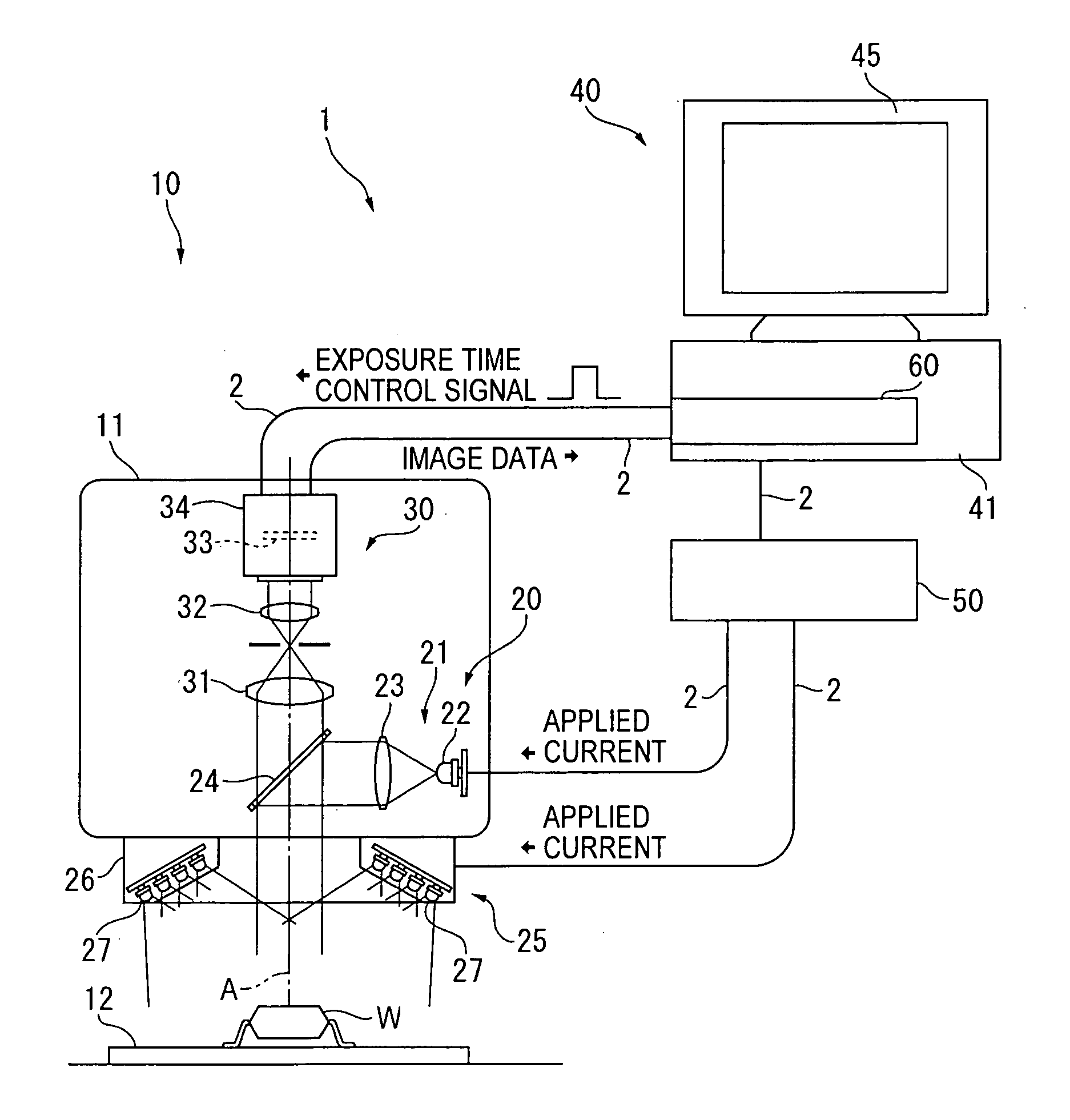
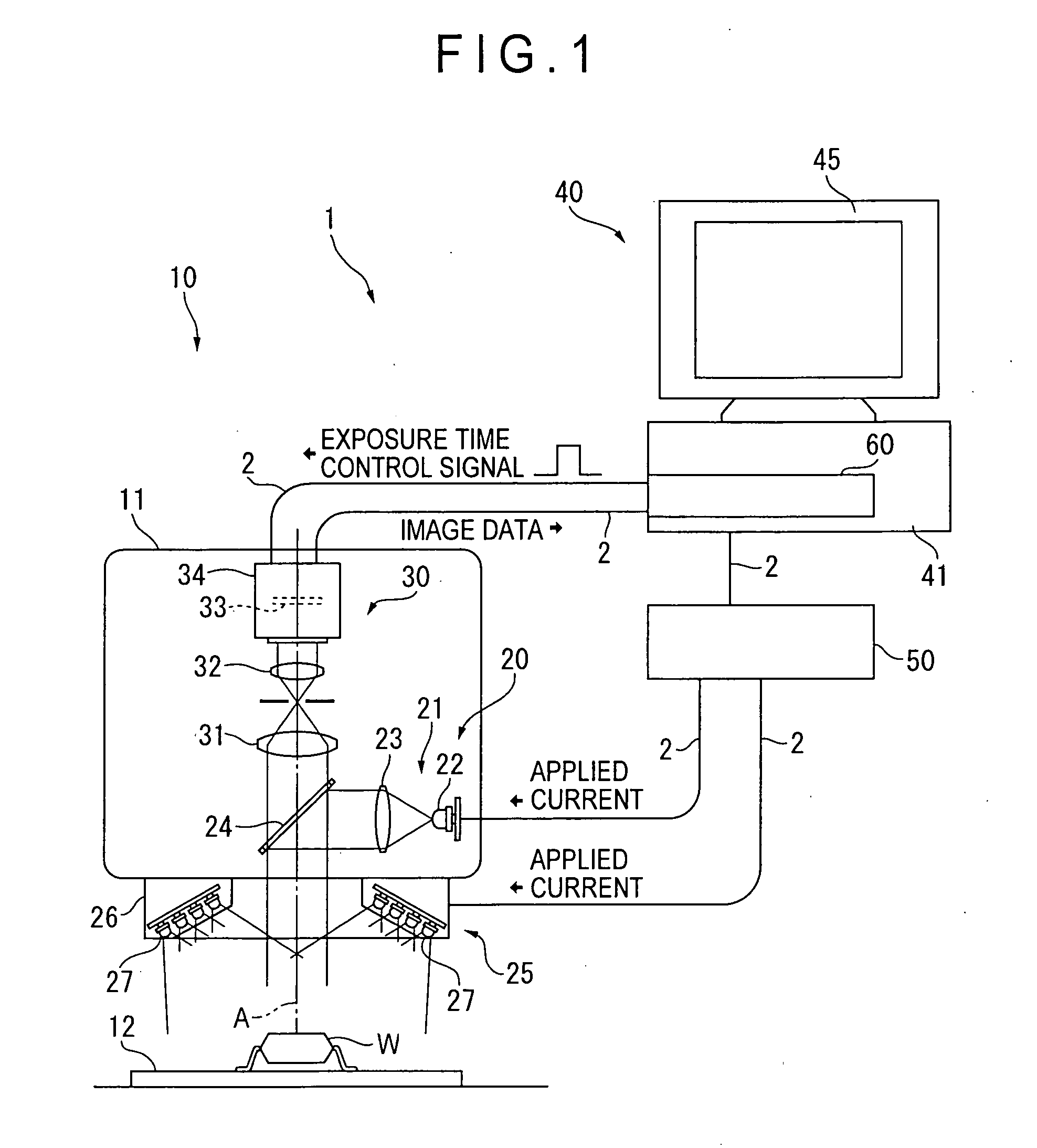
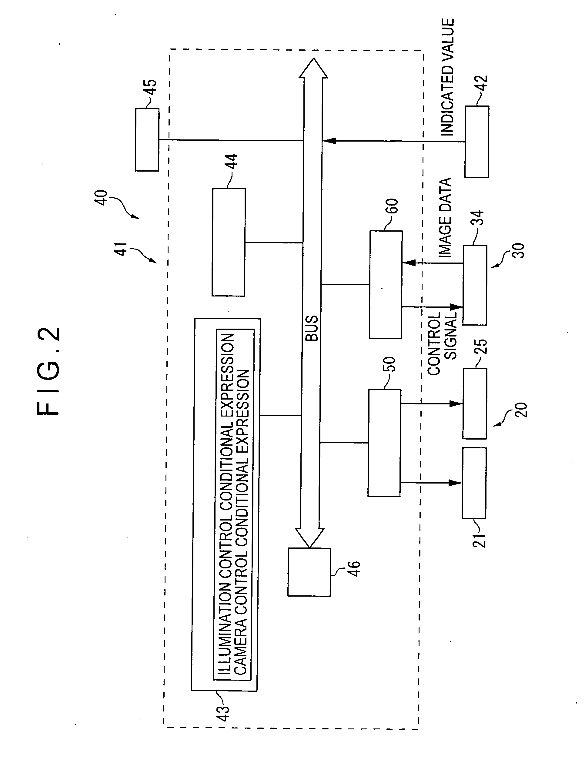
[0058] FIG. 1 is a view showing general configuration of the image measuring device 1 according to this embodiment. FIG. 2 is a block diagram showing configuration of the image measuring device 1. FIG. 3A to FIG. 3C are views each showing a relation among an indicated value, illuminance, an exposure time, and brightness of an image in the image measuring device 1. FIG. 4 is a flow chart showing an image measuring method in the image measuring device 1.

[0059] In FIG. 1, the image measuring device 1 comprises a device body 10 for irradiating illumination light to a workpiece W as a workpiece and picking up reflected light from the workpiece W, and a device controller 40 for processing an image of the workpiece W picked-up by this device body 10 and also controlling operations of the device body 10. The device body 10 and the device controller 40 are connected to each other via a cable 2.

[0060] The device body 10 comprises a housing 11 having a form like a holl...

second embodiment

[0108] [Second Embodiment]

[0109] Next a second embodiment of the present invention is described with reference to FIG. 5A to FIG. 5C.

[0110] FIG. 5A to FIG. 5C show a relation among an indicated value, illuminance, an exposure time, and brightness of an image in this embodiment.

[0111] Configuration of the image measuring device 1 and the image measuring method in this embodiment are substantially the same as those described in the first embodiment above, and is different from the first embodiment only in the expression for setting a relation among the indicated value x, illuminance L, and exposure time E. The difference is described in detail below.

[0112] The illumination control conditional expression for computing the illuminance L of the workpiece W and the camera control conditional expression for computing the exposure time E of the image pick-up unit 30 are defined in this embodiment as described below.

[0113] The prespecified indicated value is that (indicated by the sign A in ...

third embodiment

[0129] [Third Embodiment]

[0130] Next a third embodiment of the present invention is described with reference to FIG. 6A to FIG. 6C below.

[0131] FIG. 6A to FIG. 6C are views each showing a relation among an indicated value, illuminance, an exposure time, and brightness of an image.

[0132] Configuration of the image measuring device 1 and the image measuring method in this embodiment are the substantially same as those in the first embodiment described above, but are different from the first embodiment only in the expression for computing a relation among an indicated value x, illuminance L, an exposure time, and brightness of an image. The difference is described in detail below.

[0133] The illumination control conditional expression for computing illuminance L of a workpiece W and the camera control conditional expression for computing an exposure time E of the image pick-up unit 30 are defined in this embodiment as described below.

[0134] The prespecified indicated value is that corre...


PUM

PropertyMeasurementUnit
exposure timeaaaaaaaaaa
luminanceaaaaaaaaaa
brightnessaaaaaaaaaa

Abstract

An image measuring method according to the present invention comprises an illuminance computing step of computing illuminance of a workpiece (W) based on an indicated value set and inputted from the outside as well as on luminance of an illumination unit (20), and an exposure time computing step of computing an exposure time of an image pick-up unit (30). The illumination unit (20) and the image pick-up unit (30) are controlled according to the computed illuminance and exposure time to pick-up an image, so that an image satisfying both the illuminance of the workpiece (W) and an exposure time of the image pick-up unit (30) can be picked up. Therefore, even in a case in which a controllable range of luminance of the illumination device (20) is limited and the luminance can not be raised beyond the upper limit, an image having the brightness higher than the upper limit of luminance of the illumination unit (20) can be picked up by prolonging the exposure time of the image pick-up unit (30).

Description

[0001] 1. Field of the Invention[0002] The present invention relates to an image measuring method and an image measuring device. More specifically, this invention relates to an image measuring method of measuring a form or the like of a workpiece with an image measuring device comprising a luminance-variable illumination unit and an image pick-up unit by irradiating illumination light from the illumination unit to the workpiece and picking-up the reflected light from the workpiece, and measuring a form or other parameters of the workpiece from the picked-up image, and also relates to the image measuring device.[0003] 2. Description of Related Art[0004] There has been known an image measuring device comprising an illumination unit for irradiating illumination light to a workpiece and an image pick-up unit for picking-up reflected light from the workpiece and capable of measuring a form, dimensions, and colors of the workpiece by subjecting the image picked-up by the image pick-up uni...

Claims


Application Information

Patent Timeline
Patent Type & Authority Applications(United States)
IPC IPC(8): G01B11/02G01B11/24G01J3/50G01N21/01G01N21/84
CPCG01B11/02G01B11/24
Inventor YOSHIDA, HIROYUKI
Owner MITUTOYO CORP
Why Eureka
Try Eureka