Fluorescence observation apparatus

a fluorescence observation and apparatus technology, applied in the direction of fluorescence/phosphorescence, luminescent dosimeters, optical radiation measurement, etc., can solve the problems of inability to observe appropriate brightness of images and dark fluorescence images, and achieve accurate normalization of reference images, enhance quantitative fluorescence images, and appropriate brightness

Active Publication Date: 2011-05-26
OLYMPUS CORP
View PDF5 Cites 21 Cited by
  • Summary
  • Abstract
  • Description
  • Claims
  • Application Information

AI Technical Summary

Benefits of technology

[0016]When the intensity of the illumination light and the intensity of the excitation light are changed, the light intensity distribution characteristics of the illumination light and the light intensity distribution characteristics of the excitation light change in different ways from each other because of a difference in wavelength band between the illumination light and the excitation light. When the intensity correction section corrects the intensity of the illumination light and the intensity of the excitation

Problems solved by technology

However, as in the conventional fluorescence observation apparatus, if the brightness of an image is controlled just by adjusting the exposure time, there is a disadvantage that, in some cases, an image having appropriate brightness cannot be observed because a

Method used


Image

  • Fluorescence observation apparatus
  • Fluorescence observation apparatus
  • Fluorescence observation apparatus

Examples


first embodiment

[0030]A fluorescence observation apparatus according to a first embodiment of the present invention will be described below with reference to the drawings.

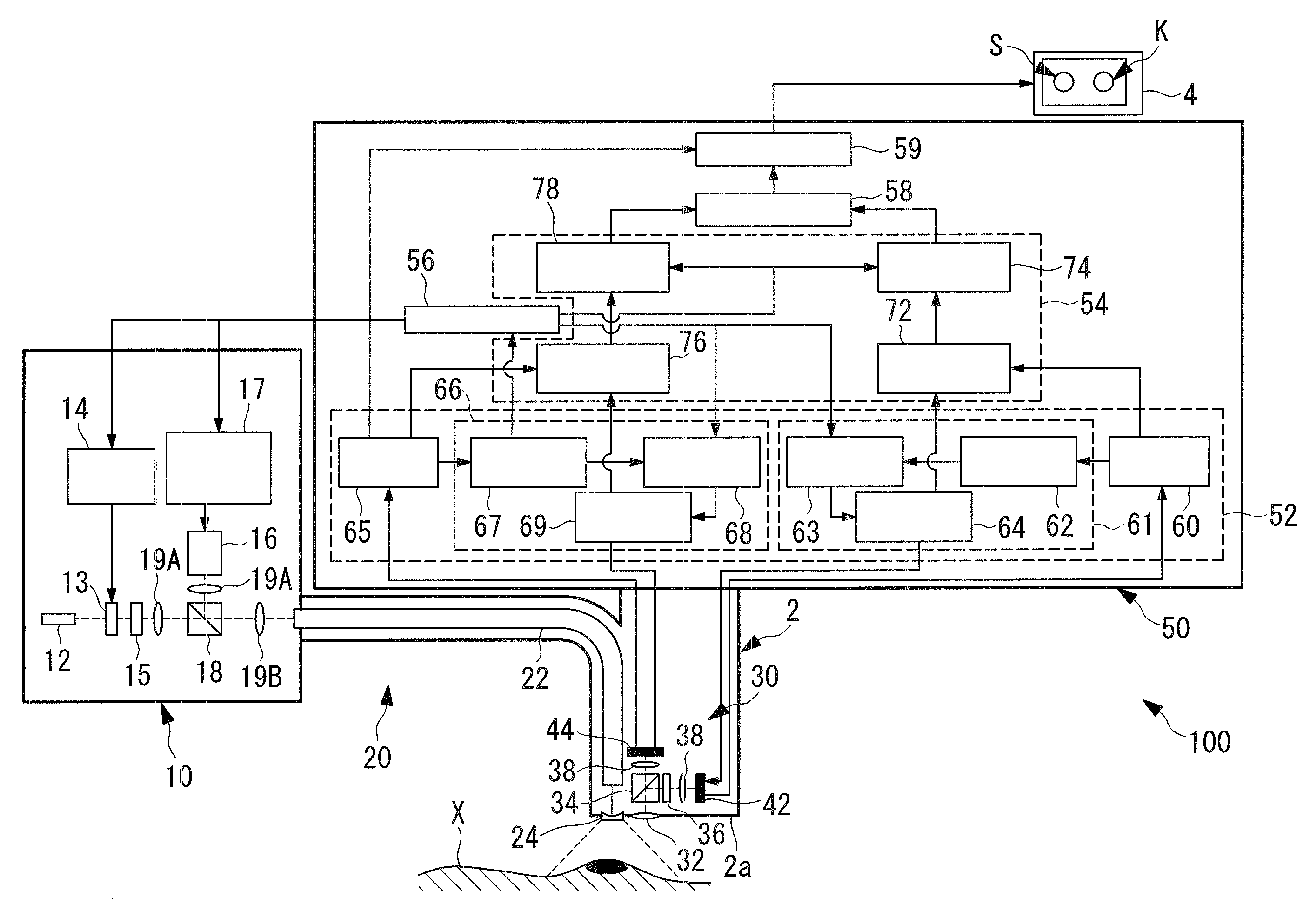
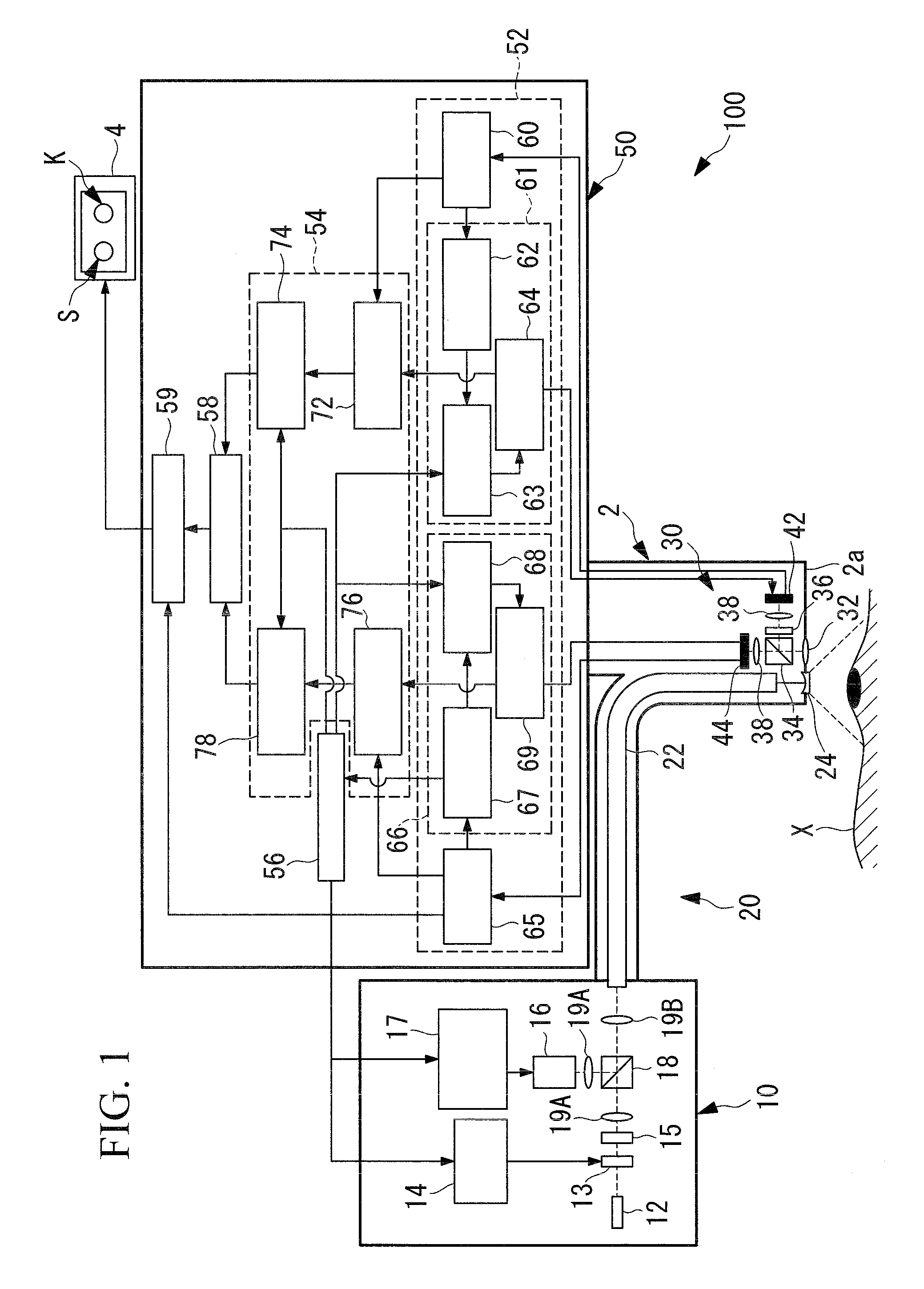
[0031]A fluorescence observation apparatus 100 according to this embodiment is a microscope apparatus and, as shown in FIG. 1, includes an elongated insertion portion 2 to be inserted into a body cavity, an illumination unit (illumination section) 20 provided with a light source 10 that outputs illumination light to be emitted from a tip 2a of the insertion portion 2, an image acquisition unit 30 that is disposed in the insertion portion 2 and that acquires image information of an observation target region X, which is a subject, an image processing section 50 that applies arithmetic processing to the image information acquired by the image acquisition unit 30, and a monitor 4 that displays an image processed by the image processing section 50 or other data.

[0032]The light source 10 includes a xenon lamp 12 that emits illumination ...

second embodiment

[0086]Next, a fluorescence observation apparatus according to a second embodiment of the present invention will be described.

[0087]As shown in FIG. 7, a fluorescence observation apparatus 200 of this embodiment differs from that of the first embodiment in that a light source 210 is not provided with the semiconductor laser 16, and the diaphragm control section 14 simultaneously controls the amounts of illumination light and excitation light emitted from the xenon lamp 12.

[0088]Identical reference symbols are assigned to the component parts common to the fluorescence observation apparatus 100 of the first embodiment, and a description thereof will be omitted.

[0089]The light source 210 includes the xenon lamp 12, the diaphragm 13, and a coupling lens 19 that converges illumination light (white light), which includes excitation light emitted from the xenon lamp 12 and passing through the diaphragm 13.

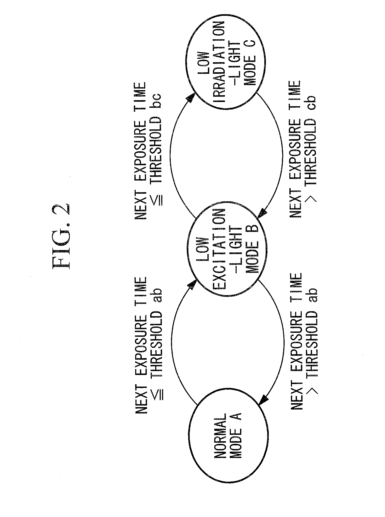
[0090]As shown in FIG. 8, the quantitativeness control section 56 has two control mode...


PUM


Abstract

A quantitative fluorescence image and appropriate brightness is acquired and observed. Provided is a fluorescence observation apparatus including: an illumination section that includes a light source for irradiating an observation target region with illumination light and excitation light; a fluorescence image acquisition section that acquires a fluorescence image from fluorescence produced in the observation target region; a white-light image acquisition section that acquires a reference image from return light returning from the observation target region; an exposure-time adjustment unit that adjusts the exposure time based on the luminance value of the reference image; a diaphragm control section and a semiconductor laser control section that control the intensity of the illumination light and that of the excitation light based on the exposure time; a first normalization section that normalizes the luminance of the reference image and the fluorescence image by the exposure time; a second normalization section that normalizes the luminance of the reference image and the fluorescence image by the light intensity; and
    • an image correction section that corrects the fluorescence image by the reference image, by using at least one of the normalized reference image or fluorescence image.

Description

BACKGROUND OF THE INVENTION[0001]1. Field of the Invention[0002]The present invention relates to a fluorescence observation apparatus.[0003]This application is based on Japanese Patent Application No. 2009-269156, the content of which is incorporated herein by reference.[0004]2. Description of Related Art[0005]In a known conventional method, a fluorescence image is divided by a reference image to acquire a quantitative fluorescence image in which a change in fluorescence intensity, depending on observation distance, has been corrected (for example, see the specification of U.S. Patent Application Publication No. 2008 / 0015446). In a fluorescence observation apparatus disclosed in the specification of U.S. Patent Application Publication No. 2008 / 0015446, the exposure time of an image acquisition device is further adjusted automatically to allow a reflected-light image and a fluorescence image to be observed at constant brightness even if the observation conditions are changed.[0006]Ho...

Claims


Application Information

Patent Timeline
IPC IPC(8): G01N21/64
CPCA61B1/043A61B1/0646A61B1/0638A61B5/0071A61B5/0084G01J1/32G01J3/02G01J3/027G01J3/10G01J3/28G01J3/2803G01J3/4406G01N21/6458G01N2021/6484A61B1/063A61B1/05A61B1/0655
Inventor WATANABE, TOSHIAKI
Owner OLYMPUS CORP
Why Eureka
Try Eureka