Keyboard switch with internal fluid containment network

a keyboard switch and fluid containment network technology, applied in the direction of contact surface shape/structure, venting, contact, etc., can solve the problems of creating chattering or bouncing of contacts, dust or water drops can penetrate, electrodes are exposed to dust or water drops, etc., to achieve the effect of improving the feel of operation

Active Publication Date: 2005-01-06
LITE ON SINGAPORE PTE LTD
View PDF11 Cites 29 Cited by
  • Summary
  • Abstract
  • Description
  • Claims
  • Application Information

AI Technical Summary

Benefits of technology

[0017] It is an object of the present invention to resolve the above-described problems and to provide a keyboard switch in which a key arrangement can be other than a linear one, the structure is sealed, and fluctuations of the inner space of the protruding member occurring during operation are released inside the keyboard switch, while the operation feel is improved.

Problems solved by technology

Such compression creates a counter force against the key-top pressing motion, thereby eventually creating chattering or bouncing of the contacts.
In above examples of the improved key switch structure, however, dust or water drops can penetrate from the upper surface of the keyboard into the inner space of the dome-like spring members or rubber caps accommodating electrodes therein.
Therefore, though the configurations of these examples are effective in terms of adjusting pressure variations in the inner space, the electrodes are exposed to dust or water drops.
Particularly, when a plurality of projecting portions 207 are pushed down at the same time, the capacity of the air escape path is insufficient thus preventing adequate air escape.
As a result, an undesirable effect on user's fingers can be produced during push-down action of the projecting portions 207.
However, the drawback of such a configuration is that when a plurality of key tops 150 are pushed down at the same time, the quantity of air that is moved by such a push-down action cannot be contained within the elongated holes.
Moreover, the volume of air allowed to escape is limited by the small size of ventilation holes 130g reducing the flow rate of air and adversely affecting the process of keying on this keyboard.
Moreover, because the above-described linking channel has a complex structure, which is divided into the upper and lower spaces, the upper and lower spaces cannot be composed as one general space or support.

Method used


Image

  • Keyboard switch with internal fluid containment network
  • Keyboard switch with internal fluid containment network
  • Keyboard switch with internal fluid containment network

Examples


first embodiment

[0038]FIG. 3 illustrates the supports of various types suitable for supporting the protruding member in accordance with the present invention. (Even though the various supports illustrated in FIG. 3 can also be used with other embodiments of the present invention, the explanation will only be conducted with respect to the )

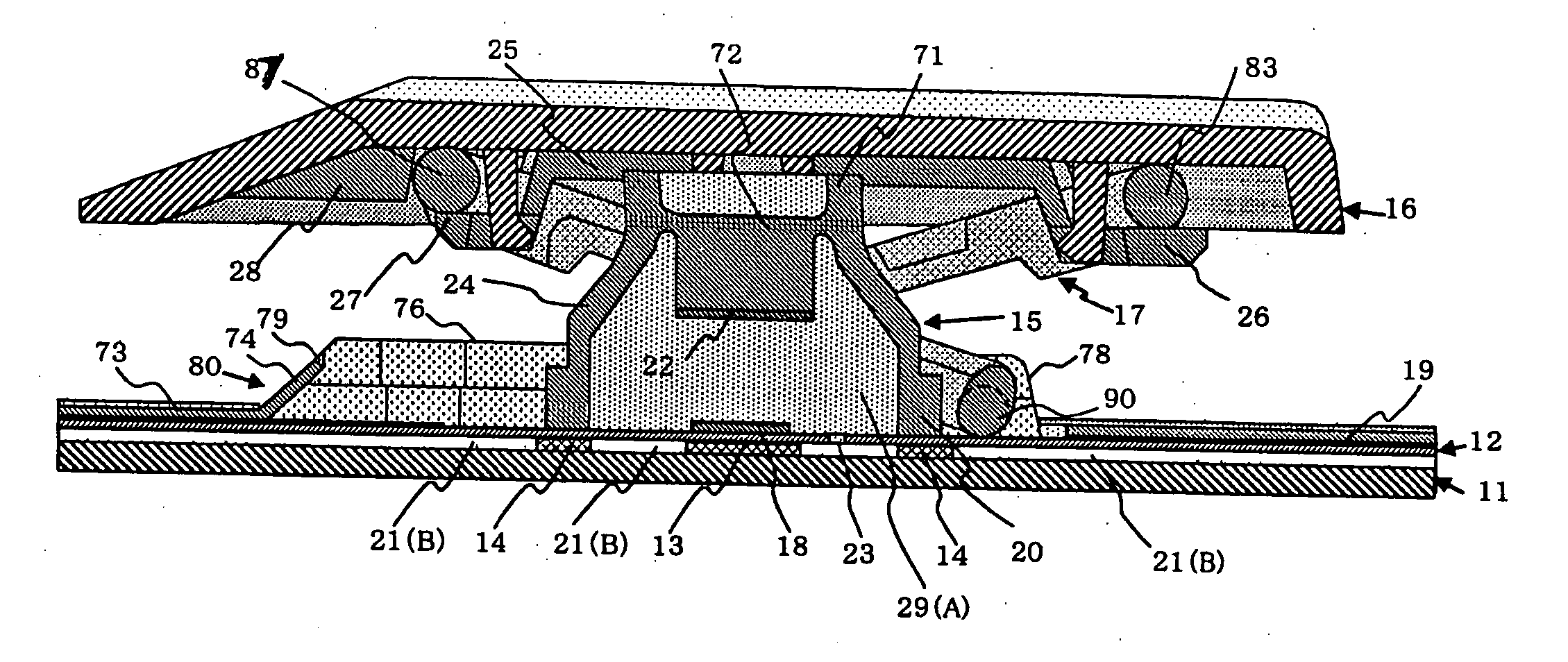
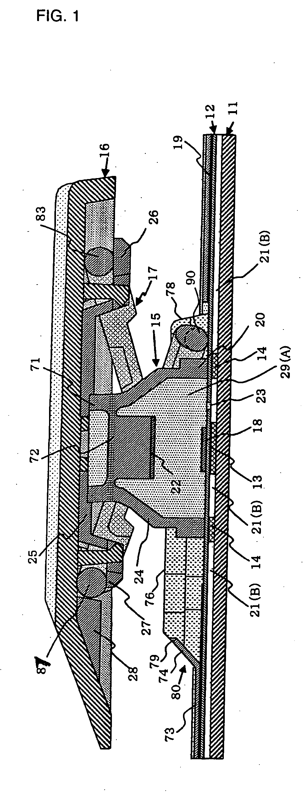
[0039] The main purpose of using the supports 13 and 14 is to bear the push-down load when the key top 16 is pushed down. More specifically, they support the fixed electrode 18 to which a load is applied via a movable electrode 22, and the collar 20 to which a load is applied via the skirt portion 24 of the rubber cap 15. Additionally, supports 13 and 14 define boundaries of space 21(B) for accommodating the air or other fluid present inside the rubber cap 15 in the keyboard switch. The supports are formed to a predetermined height above the surface of the membrane sheet 12.

[0040]FIG. 3(a) shows a type A support in which a round fixed electrode support 13 wider t...

third embodiment

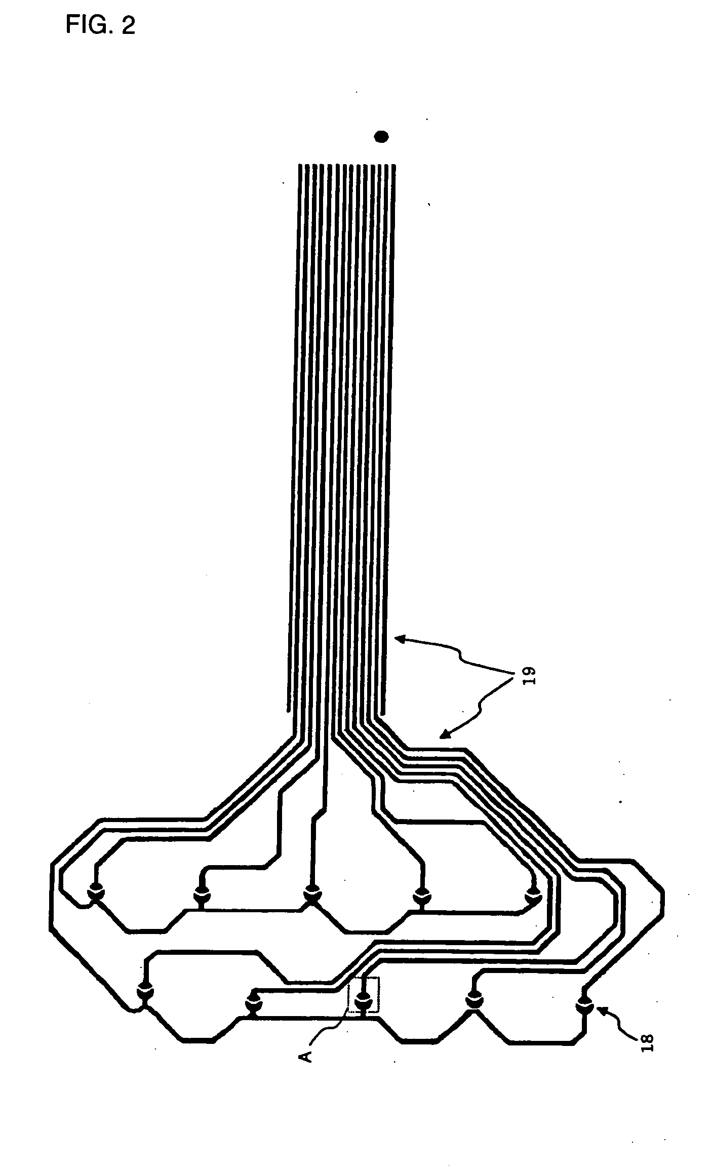
[0077]FIG. 7, a structural view of the present invention, provides a lower surface view of the membrane sheet (plane view of the back side surface). FIG. 7(b) is a cross-sectional view of a rectangular region (represented by dotted lines) shown by C-C′ in FIG. 7(a), which is a cross-sectional view of the space from the back side surface of the membrane sheet (structural components located on the front surface side are omitted) to the base plate.

[0078] In the third embodiment shown in FIG. 7, the structure from the membrane sheet to the base plate that was employed in the first embodiment and second embodiment is a completely sealed structure, except for the ventilation hole. A partition wall 100 surrounding the surface of the membrane sheet 12 and base plate 11 is provided at either of the opposing surfaces thereof, and a sealed space having no holes except for the ventilation hole 23 is bounded by the membrane sheet 12, base plate 11, and partition wall 100.

[0079] In the structure...


PUM


Abstract

A keyboard switch with an internal air escape network, such as a series of channels or through holes, for containing air or fluid escaping from the switching cavities when a key is depressed.

Description

CROSS-REFERENCE TO RELATED APPLICATIONS [0001] This application claims all rights of priority to Japanese Patent Application Serial No. 2003-175262, filed Jun. 19, 2003 (pending). BACKGROUND OF THE INVENTION [0002] The present invention relates to the switching mechanisms used in keyboards for various electronic devices, particularly personal notebook computers in which the keyboard is disposed above the inner circuitry. DESCRIPTION OF THE RELATED ART [0003] The conventional mechanisms for converting a key-top pressing motion into a switching action of an electric contact, such as is found in a keyboard switch, generally include two types. The first utilizes a rubber cap connected to the key top, where the rubber cap is typically in the shape of an edgeless hat or cup. The second type utilizes a dome-like spring body serving as the key top. Additionally, either type of the described conventional types of keyboard switches may come in two distinct varieties. In the first, the contact...

Claims


Application Information

Patent Timeline
Patent Type & Authority Applications(United States)
IPC IPC(8): H01H3/12H01H13/14H01H13/06H01H13/70H01H13/702H01H13/82
CPCH01H3/125H01H2213/014H01H2213/002H01H13/82
Inventor YONEYAMA, MASAYUKI
Owner LITE ON SINGAPORE PTE LTD
Why Eureka
Try Eureka