Column network hardware management system

Active Publication Date: 2005-01-13
HUBBELL INC
View PDF21 Cites 25 Cited by
  • Summary
  • Abstract
  • Description
  • Claims
  • Application Information

AI Technical Summary

Benefits of technology

[0006] Accordingly, an object of the present invention is to provide a column network hardware manag

Problems solved by technology

These current systems, however, are costly due to the requirement of multiple racks and channels to support the electrical equipment.
Addi

Method used


Image

  • Column network hardware management system
  • Column network hardware management system
  • Column network hardware management system

Examples


Example

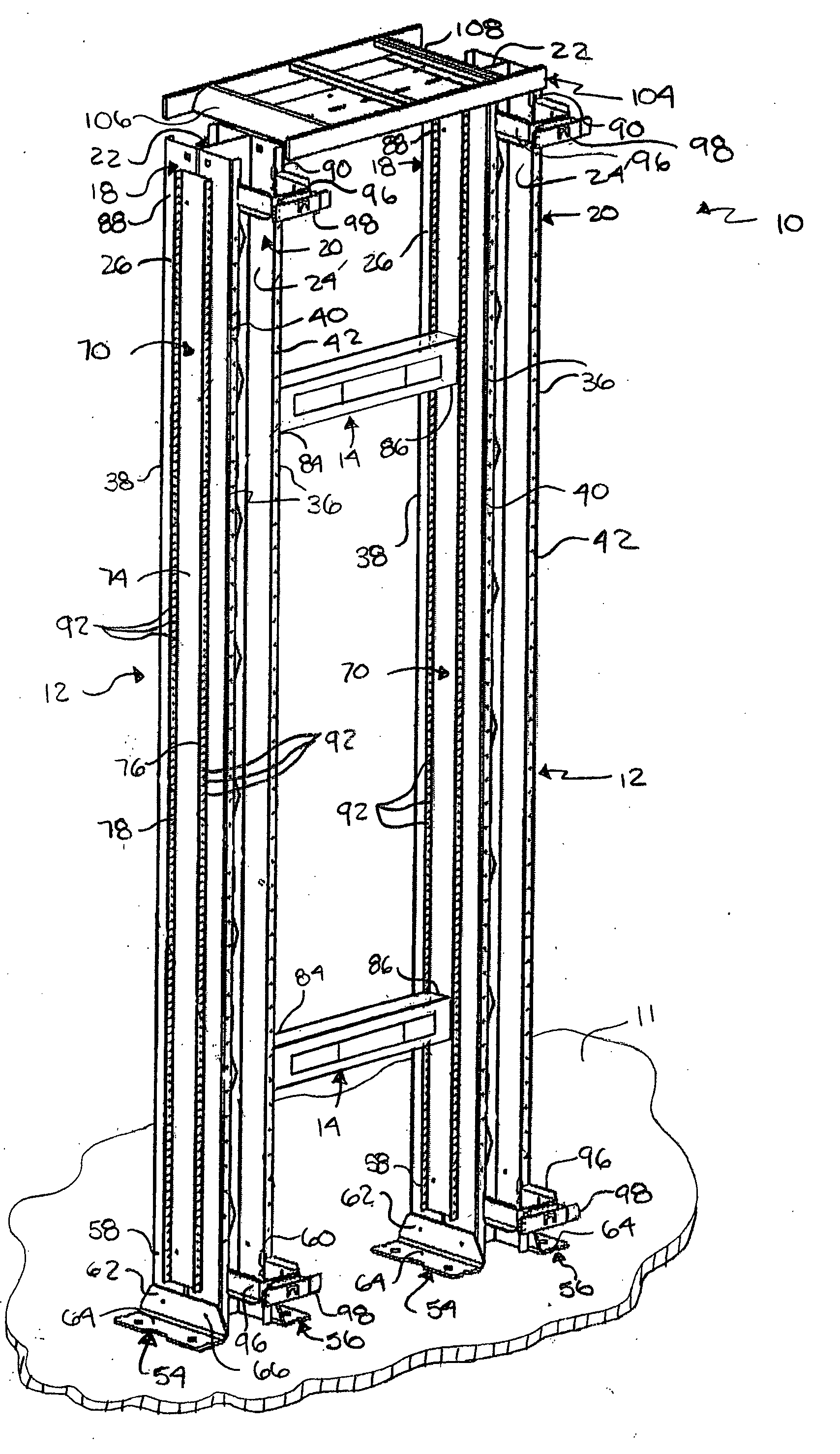
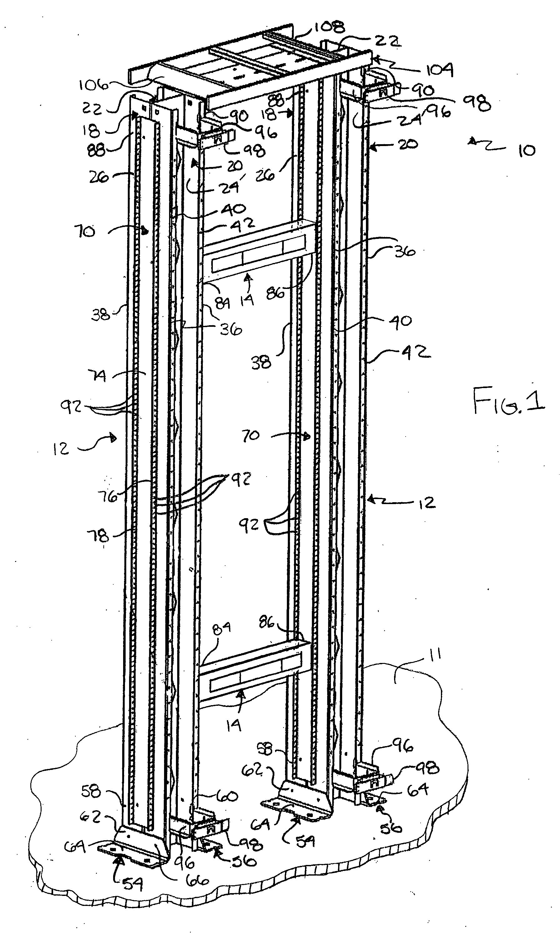
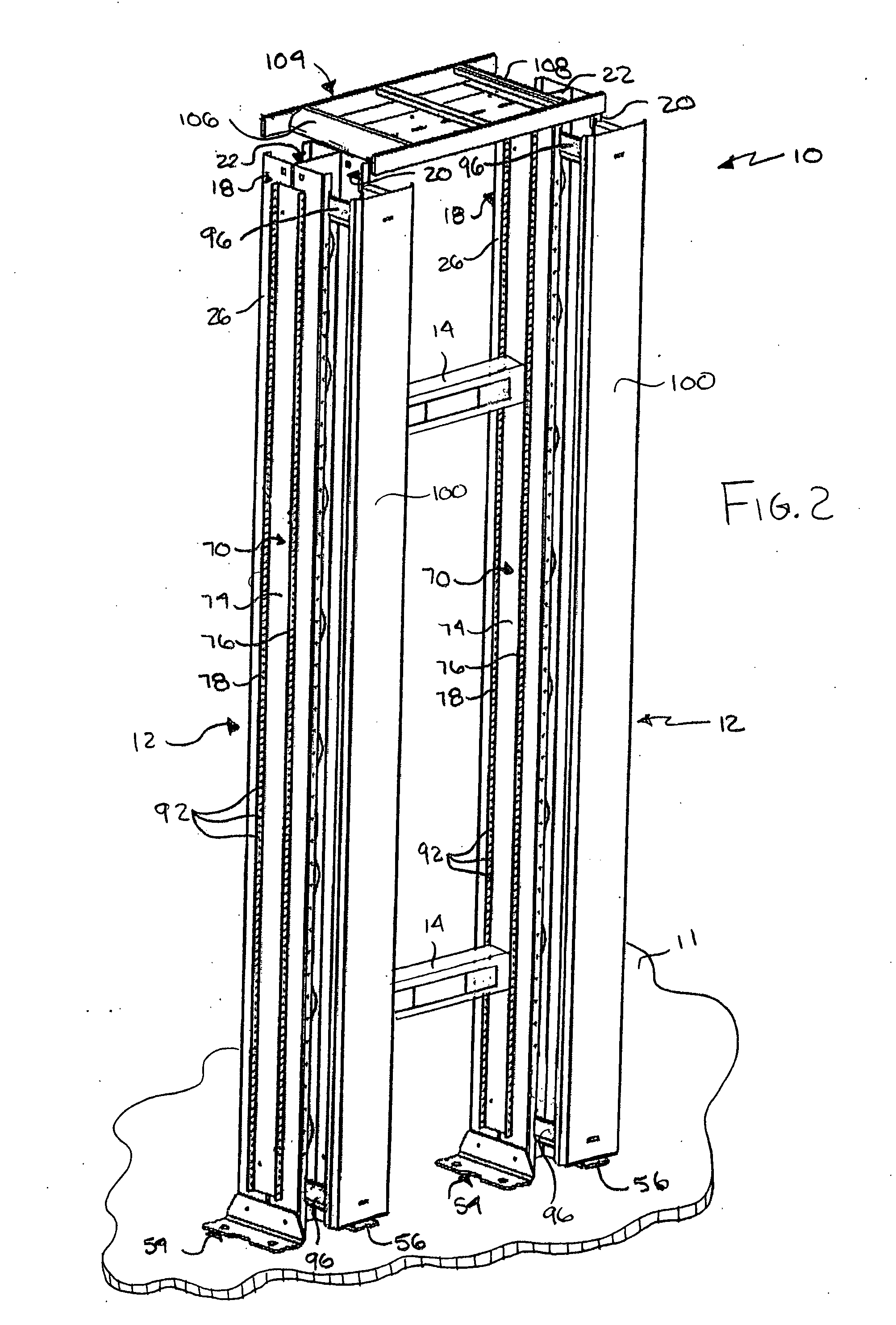
[0019] Referring to FIGS. 1-5, a management system 10 according to a preferred embodiment of the present invention integrates the functions of a rack for supporting electrical equipment and channels for managing cabling of the equipment. More specifically, system 10 includes management channels 12 that both support electrical equipment 14 and manage cabling 16 of the equipment, thereby eliminating the necessity of a separate equipment rack. Channels 12 are supported on a surface, such as floor 11.

[0020] As seen in FIG. 3, each management channel 12 includes first and second vertical members 18 and 20. A third member 22 extends between and connects first and second vertical members 18 and 20. First, second and third members 18, 20 and 22 preferably form an I-shaped channel in section transverse to the longitudinal axis of channel 12, as seen in FIG. 4. However, first, second and third members 18, 20 and 22 can form any shaped channel, such as a Z-shaped or C-shaped channel. Each of ...


PUM


Abstract

A channel for managing equipment cables that includes opposing first and second members and a third member extending between and connecting the first and second members. Each of the first and second members includes first and second inner and outer surfaces. At least one cable receiving area is defined between the first and second inner surfaces of the first and second members. First and second equipment mounting elements extend from each of the first and second outer surfaces of the first and second members. The first and second equipment mounting elements are connectable to equipment. A base support is coupled to at least one of the first and second members.

Description

FIELD OF THE INVENTION [0001] The present invention relates to a column network hardward management system designed to support electrical equipment and manage the cabling of the equipment. More specifically, self-supporting channels support the equipment and provide receiving areas for managing the cabling of the equipment. BACKGROUND OF THE INVENTION [0002] Conventional cable or hardware management systems and relay racks provide a method of supporting electrical equipment and managing the cabling associated with the equipment. Typically, these systems or racks are used in a termination closet for the management of telecommunication equipment. [0003] Current cable or hardware management systems include separate channels that are mounted on the sides of the rack supporting the equipment, as disclosed in U.S. Pat. No. 6,347,714 to Fournier et al., the subject matter of which is hereby incorporated by reference. Fournier et al. discloses a rack 20 including left and right vertical mem...

Claims


Application Information

Patent Timeline
IPC IPC(8): H02G3/04
CPCH02G3/0493
Inventor ABBY, MARJANA M.BAXTER, ROBERT C.MILLER, ALAN C.HERRING, NATHANIEL L.
Owner HUBBELL INC
Why Eureka
Try Eureka