Compressed gas tank for a motor vehicle

a technology for compressed gas and motor vehicles, which is applied in the direction of items transportation vehicles, containers, understructures, etc., can solve the problems of poor utilization of existing installation volume of conventional compressed gas bottles, limited installation space available in motor vehicles for compressed gas tanks, and short driving range of motor vehicles, so as to achieve the effect of increasing rigidity

Inactive Publication Date: 2005-01-20
BENTELER AUTOMOBILTECHNIK GMBH
View PDF4 Cites 40 Cited by
  • Summary
  • Abstract
  • Description
  • Claims
  • Application Information

AI Technical Summary

Benefits of technology

[0007] According to one aspect of the present invention, a compressed gas tank for a motor vehicle includes a metallic gas container having opposite container walls which are constructed with a profiling to increase rigidity, and at least one tie element extending across the gas container.

Problems solved by technology

However, the installation space available in motor vehicles is very limited for compressed gas tanks.
Conventional compressed gas bottles allow only poor exploitation of the existing installation volume, i.e. only a very small amount of compressed gas can be made available so that the driving range of a motor vehicle is too short.
While current joining techniques are able to maintain sufficient tightness of the gas container, there is the problem of reaching the limit of the admissible strength of the gas container at the prevailing high internal container pressure.

Method used


Image

  • Compressed gas tank for a motor vehicle
  • Compressed gas tank for a motor vehicle
  • Compressed gas tank for a motor vehicle

Examples


first embodiment

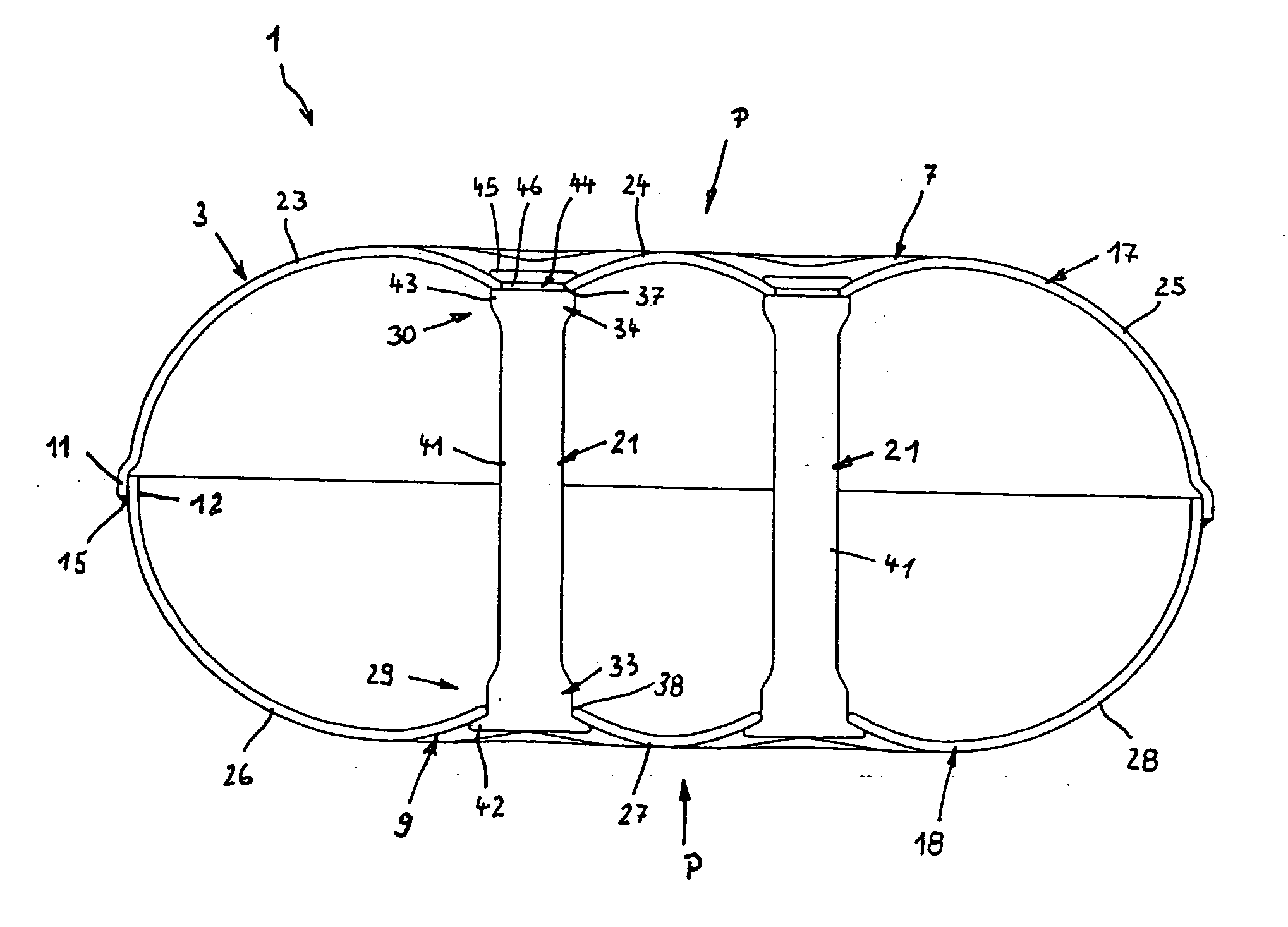
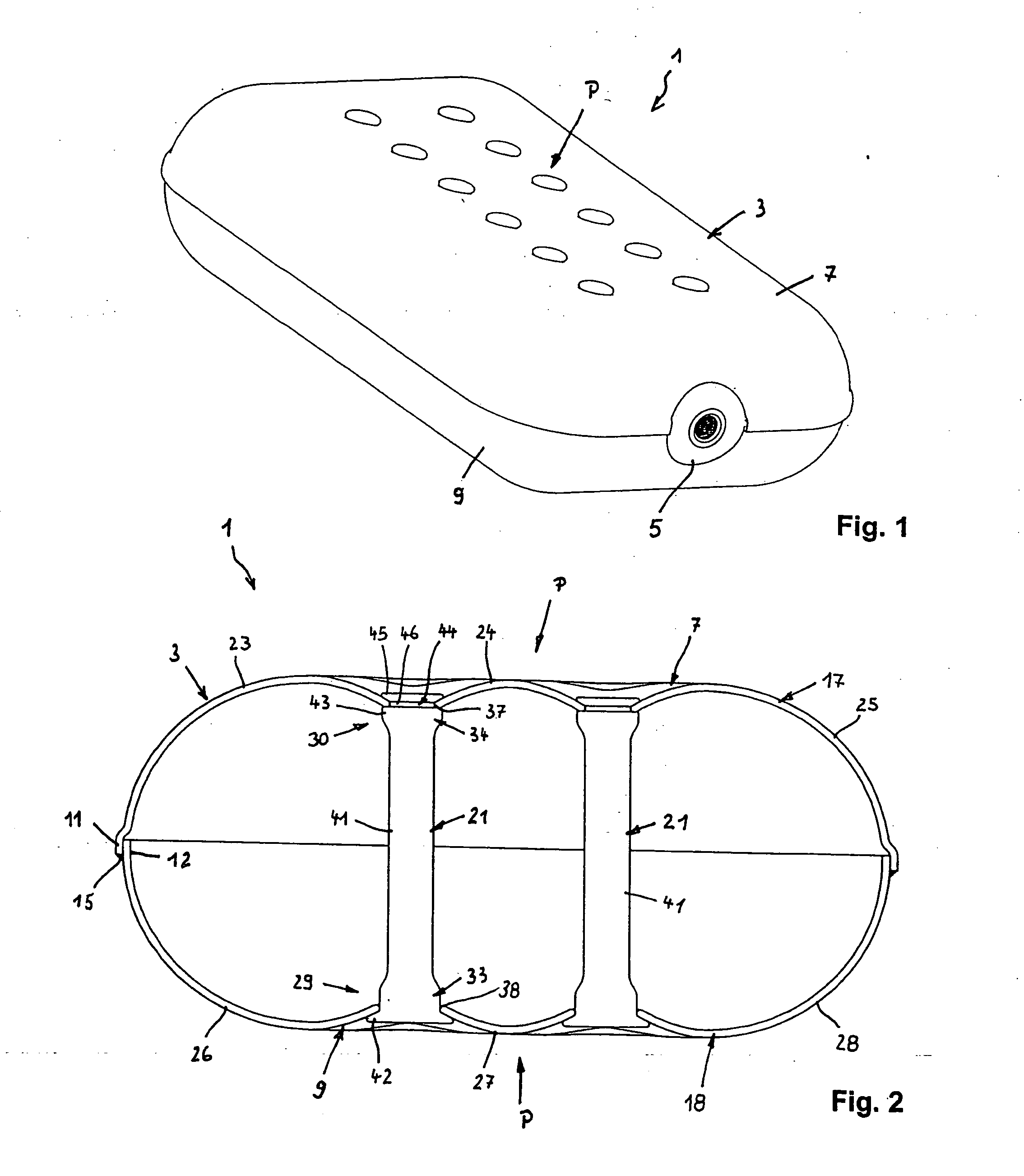
[0029] Turning now to the drawing, and in particular to FIG. 1, there is shown a perspective view of a compressed gas tank according to the present invention, generally designated by reference numeral 1 and including a metallic gas container 3 having a connection port 5 for introduction or withdrawal of compressed gas into or from the interior of the gas container 3. The gas container 3 has an elongated generally rectangular configuration with rounded side regions. Of course, the gas container 3 may have any suitable shape to conform to the available installation space in a motor vehicle. In this way, the existing installation space can be used in an optimum manner.

[0030] As shown in conjunction with FIG. 2, the gas container 3 is comprised of an upper shell 7 and a lower shell 9 which are connected about their circumferential edges 11, 12, e.g. by a continuous welded seam 15. In the non-limiting example of FIG. 2, the edge 11 of the upper shell 7 is drawn outwardly to overlap the l...

second embodiment

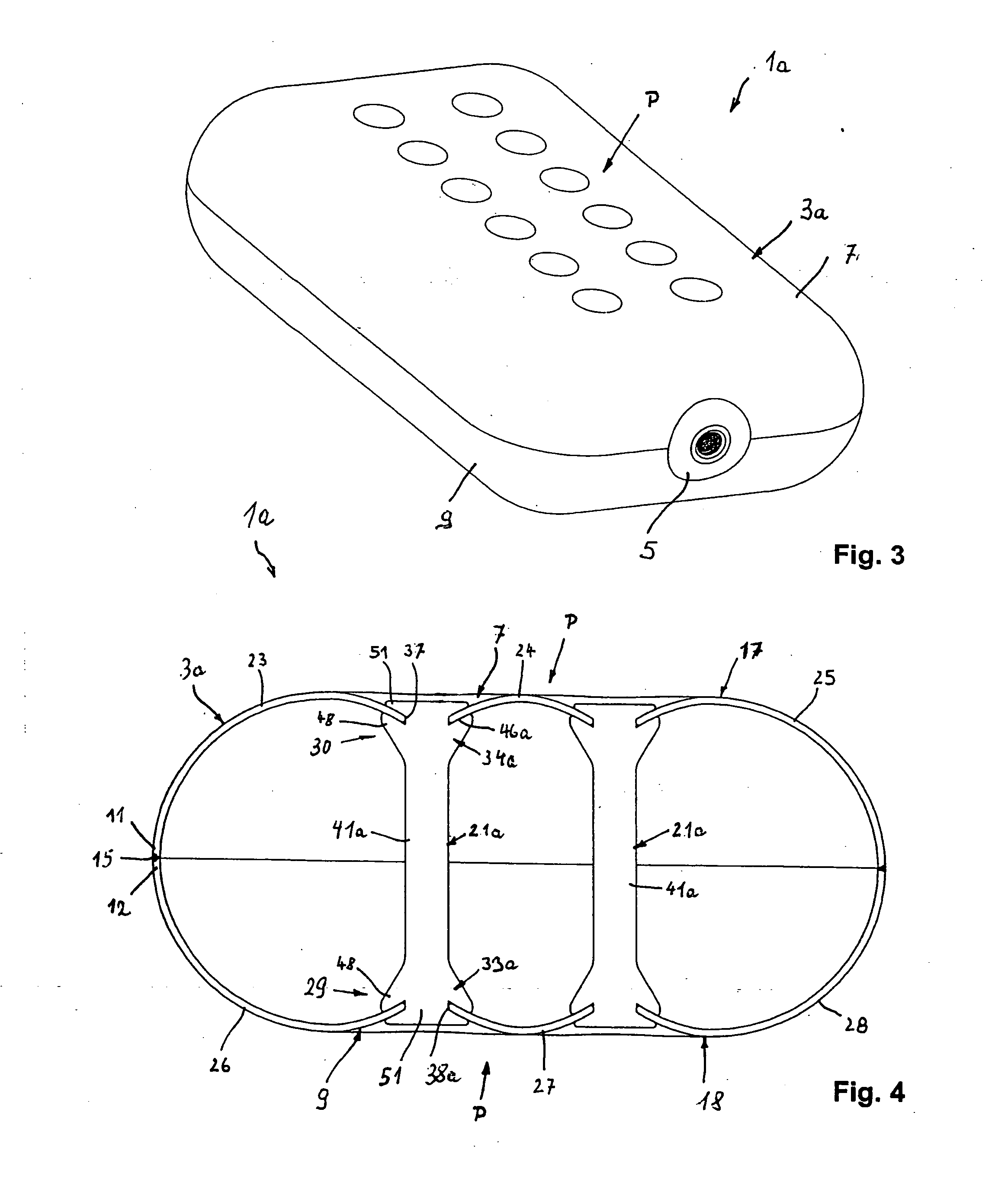
[0037] Turning now to FIG. 3, there is shown a perspective view of a compressed gas tank according to the present invention, generally designated by reference numeral 1a. In describing the embodiment of FIG. 3, parts corresponding with those in FIG. 1 will generally be identified by corresponding reference numerals followed by an “a”. The description below will generally center on the differences between the embodiments. In this embodiment, the edge 11 of the upper shell 7 of the gas container 3a and the edge 12 of the lower shell 9 form a butt joint and are welded together there by circumferential seam 15. As shown in particular in FIG. 4, which is a sectional view of the compressed gas tank 1a, each of the tie elements 21a is configured as a tie rod 41a whose opposite ends 29, 30 are formed with anchoring heads 33a, 34a having an inner stop member 48 in the form of a circumferential collar. Connected to the stop member 48 is formed initially with a pin 44a, as shown in FIG. 5, bef...


PUM


Abstract

A compressed gas tank for a motor vehicle includes a metallic gas container having opposite container walls which are constructed with a profiling to increase rigidity, and at least one tie element extending across the gas container. The profiling is realized by stamping a plurality of wall portions from the plane of the container walls to assume a convex and/or concave configuration.

Description

CROSS-REFERENCES TO RELATED APPLICATIONS [0001] This application claims the priority of German Patent Application, Serial No. 103 29 990.4, filed Jul. 2, 2003, pursuant to 35 U.S.C. 119(a)-(d), the disclosure of which is incorporated herein by reference.BACKGROUND OF THE INVENTION [0002] The present invention relates, in general, to a compressed gas tank for a motor vehicle. [0003] For some time, the automobile industry has undertaken efforts to replace currently used liquid fuels, such as gasoline or diesel fuel, with gaseous propellants for ecological reasons, because gaseous propellants can be operated with little release of pollutants. Examples of propellants that are predominantly envisioned at this time include hydrogen or natural gas. [0004] In order to ensure an adequate range for gas-propelled motor vehicles, it is required to sufficiently compress gas to enable installation of a compressed gas tank in the available space in the motor vehicle. However, the installation spac...

Claims


Application Information

Patent Timeline
Patent Type & Authority Applications(United States)
IPC IPC(8): B60K15/03F17C1/14
CPCB60K15/03006Y02E60/321F17C2201/0147F17C2201/056F17C2203/012F17C2203/013F17C2203/0617F17C2203/0636F17C2205/0332F17C2209/22F17C2209/221F17C2209/23F17C2209/232F17C2221/012F17C2221/033F17C2223/0123F17C2223/035F17C2250/03F17C2260/011F17C2260/012F17C2270/0168F17C1/14Y02E60/32
Inventor AUSTERHOFF, NORBERTPERSKE, JOACHIMBENDLER, JENSPETERS, RAFAEL
Owner BENTELER AUTOMOBILTECHNIK GMBH
Why Eureka
Try Eureka