Method and apparatus for accelerating throughput in a wireless or other telecommunication system

a wireless or other telecommunication system and throughput optimization technology, applied in the field of telecommunication applications, can solve the problems of slowing down the transmission rate at the sender, the state of the new path may be quite different, and the current tcp is not designed to cope with such a wide fluctuation in congestion, so as to achieve the effect of accelerating the transmission rate of the sender, reducing congestion, and reducing the number of calls

Active Publication Date: 2005-01-20
RPX CORP
View PDF18 Cites 84 Cited by
  • Summary
  • Abstract
  • Description
  • Claims
  • Application Information

AI Technical Summary

Problems solved by technology

Because the path can change, the congestion status on the new path may be quite different from the one on the old path, and current TCP is not designed to cope with such a wide fluctuation in congestion.
With a cautious approach, a path change will always result in slowing the transmission rates at the sender, at least initially.
Although TCP is able to adjust, it may take several RTT before all the available bandwidth is utilized.
In those cases, it is not optimal to reduce the transmission rate (even if only initially), and gradually increase it.
In addition, the regular TCP slow start (even without terminal mobility) with a small initial congestion window results in a significant throughput slowdown.
This is a particularly severe problem for short-lived connections where there is no time to amortize the cost of slow start.
Also the throughput suffers where the RTT can be large, as in the case of cellular systems.
Currently, for the Internet, there are proposals to inform the TCP sender of network congestion in any path, proposals such as in RFC2581 and as in Explicit Congestion Notification from RFC2481, but these proposals fail to specifically take mobility into account.
However, the delay-bandwidth-product on the wireless link does not indicate the congestion state of the network; it only informs about the capacity of that particular link.

Method used


Image

  • Method and apparatus for accelerating throughput in a wireless or other telecommunication system
  • Method and apparatus for accelerating throughput in a wireless or other telecommunication system
  • Method and apparatus for accelerating throughput in a wireless or other telecommunication system

Examples


Embodiment Construction

The description here uses the following definitions, which all have to do with TCP applications of the invention, although the invention is also of use in case of communication by TCP or any similar protocol, including e.g. streaming protocols such as RTCP or datagram protocols. SEGMENT: A segment is any TCP / IP data or acknowledgment packet (or both), or a corresponding entity for communication according to other packet-based protocols. RECEIVER WINDOW (rwnd) The most recently advertised receiver window. CONGESTION WINDOW (cwnd): A TCP (or other packet-based protocol) state variable that limits the amount of data a TCP layer can send. At any given time, according to standard operating procedure, a TCP layer does not send data with a sequence number higher than the sum of the highest acknowledged sequence number and the minimum of cwnd and rwnd. INITIAL WINDOW (iwnd): Initial size of congestion window at the sender (i.e. the size at the start of a TCP session).

OVERVIEW OF THE I...


PUM


Abstract

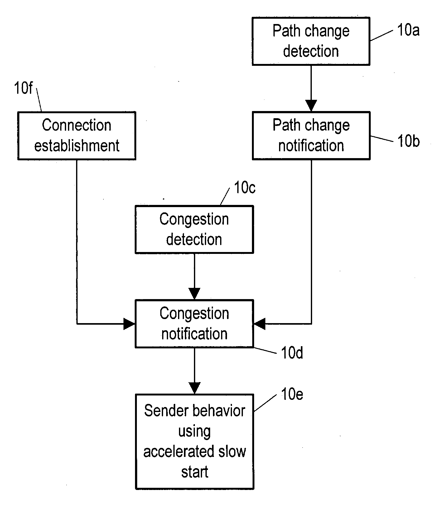
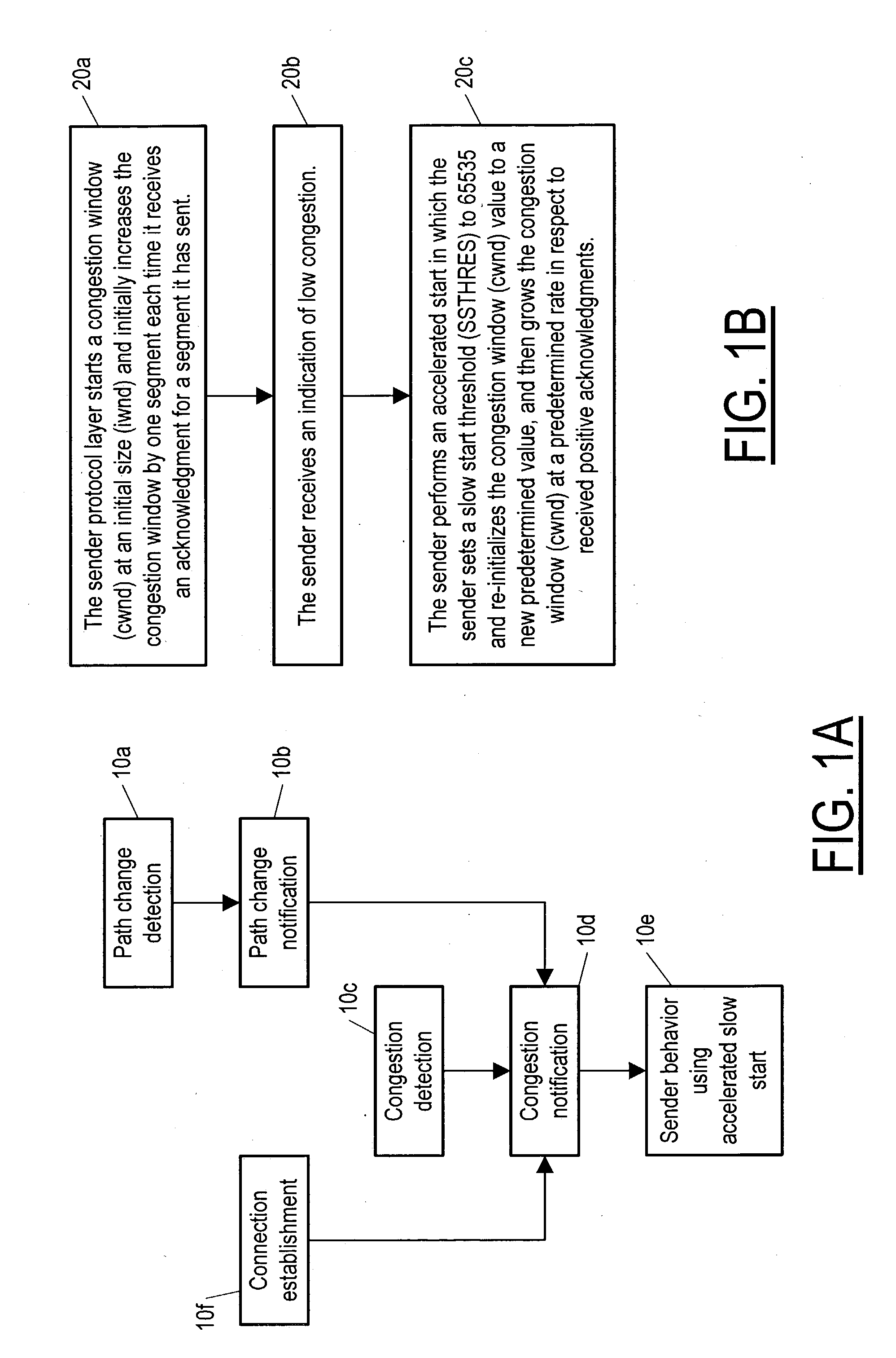
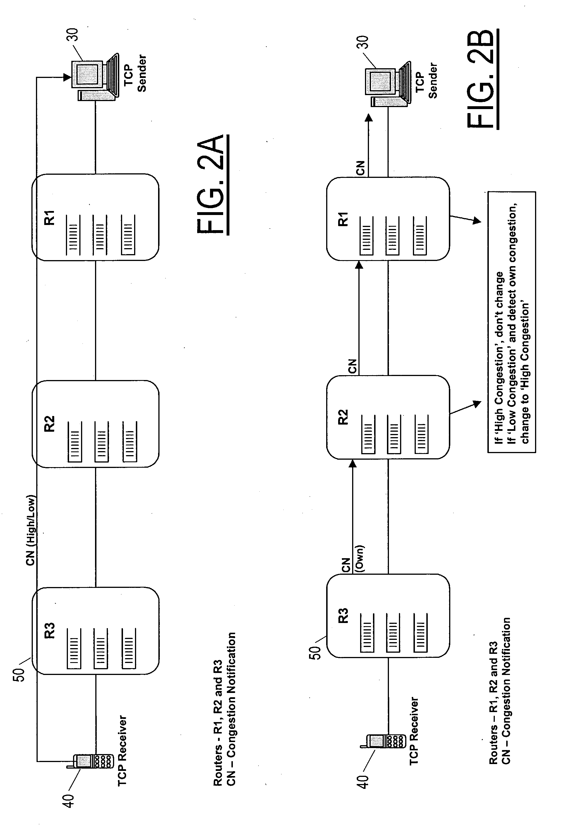
A method and equipment for accelerating throughput of communication segments from a sender (30) to a receiver (40) each of which include a protocol layer (30a 40a) for providing such segments, the method in case of TCP including a first step (20a) in which the sender protocol layer (30a) initializes a congestion window (cwnd) to some initial size (iwnd) and increases the congestion window by one segment each time it receives an ACK, but upon receiving an indication of low congestion, performs a step (20c) of accelerated start in which it sets a slow start threshold (SSTHRES) to a standard initial value (typically 65535) and re-initializes cwnd to a new value, and the sender protocol layer (30a) then increments cwnd at one or another predetermined rate—depending on whether the start immediately follows a new connection or instead follows a transfer of an existing connection to a new path—in respect to received ACKs.

Description

TECHNICAL FIELD The present invention relates to telecommunication applications including e.g. streaming protocols such as RTP (Real Time Protocol) and the newly emerging DCCP (Datagram Congestion Control Protocol) for which it is beneficial for the sending application to optimally adjust its transmission rate to operate at the highest possible throughput with minimal congestion. More particularly, the present invention pertains to throughput and congestion optimization for TCP (Transmission Control Protocol) and streaming protocol applications in fixed and mobile environments. DISCUSSION OF RELATED ART Current TCP / IP (Transmission Control Protocol / Internet Protocol) applications use congestion detection mechanisms to determine the congestion status on the path between the sender and receiver and control congestion by adopting well-known rate control mechanisms at the TCP sender side. Congestion is deemed to happen when packet loss is detected, e.g. through time-out at the sender,...

Claims


Application Information

Patent Timeline
Patent Type & Authority Applications(United States)
IPC IPC(8): H04LH04L1/00H04L12/26
CPCH04L1/0002H04L1/0015H04L1/1671H04L1/187H04L47/10H04L47/18H04L69/163H04L47/263H04L47/27H04W28/10H04W74/085H04W84/12H04L69/16H04L47/193
Inventor SREEMANTHULA, SRINIVASSWAMI, YOGESHLE, KHIEM
Owner RPX CORP
Why Eureka
Try Eureka