Line boring machine

a boring machine and boring technology, applied in the direction of portable drilling machines, drilling/boring measurement devices, manufacturing tools, etc., can solve the problems of workpiece lifting off, wood chips tend to clog up the holes, and inefficient dual power transmission systems

Active Publication Date: 2005-01-20
TUCKER BRADLEY J
View PDF8 Cites 22 Cited by
  • Summary
  • Abstract
  • Description
  • Claims
  • Application Information

AI Technical Summary

Benefits of technology

[0008] In an embodiment of the present invention, a line boring machine is provided for the purpose of boring holes in a bottom surface of a work piece. The line boring machine may comprise a bed, drill, clamp, drill linkage system, clamp linkage system and a lever. The mechanical relationship between the lever, drill linkage system and clamp linkage system enables the clamp linkage system to advantageously produce a self-adjusting downward clamp force onto the work piece which is always greater than an upward drill force exerted by the drill through the drill linkage system.

Problems solved by technology

When the holes are drilled from above, wood chips tends to clog up the holes.
This dual system of power transmission is inefficient because it requires constant adjustment and more parts.
This situation would cause the work piece to lift off the bed and become unstable thereby the holes may not be properly positioned.

Method used


Image

  • Line boring machine
  • Line boring machine
  • Line boring machine

Examples


Embodiment Construction

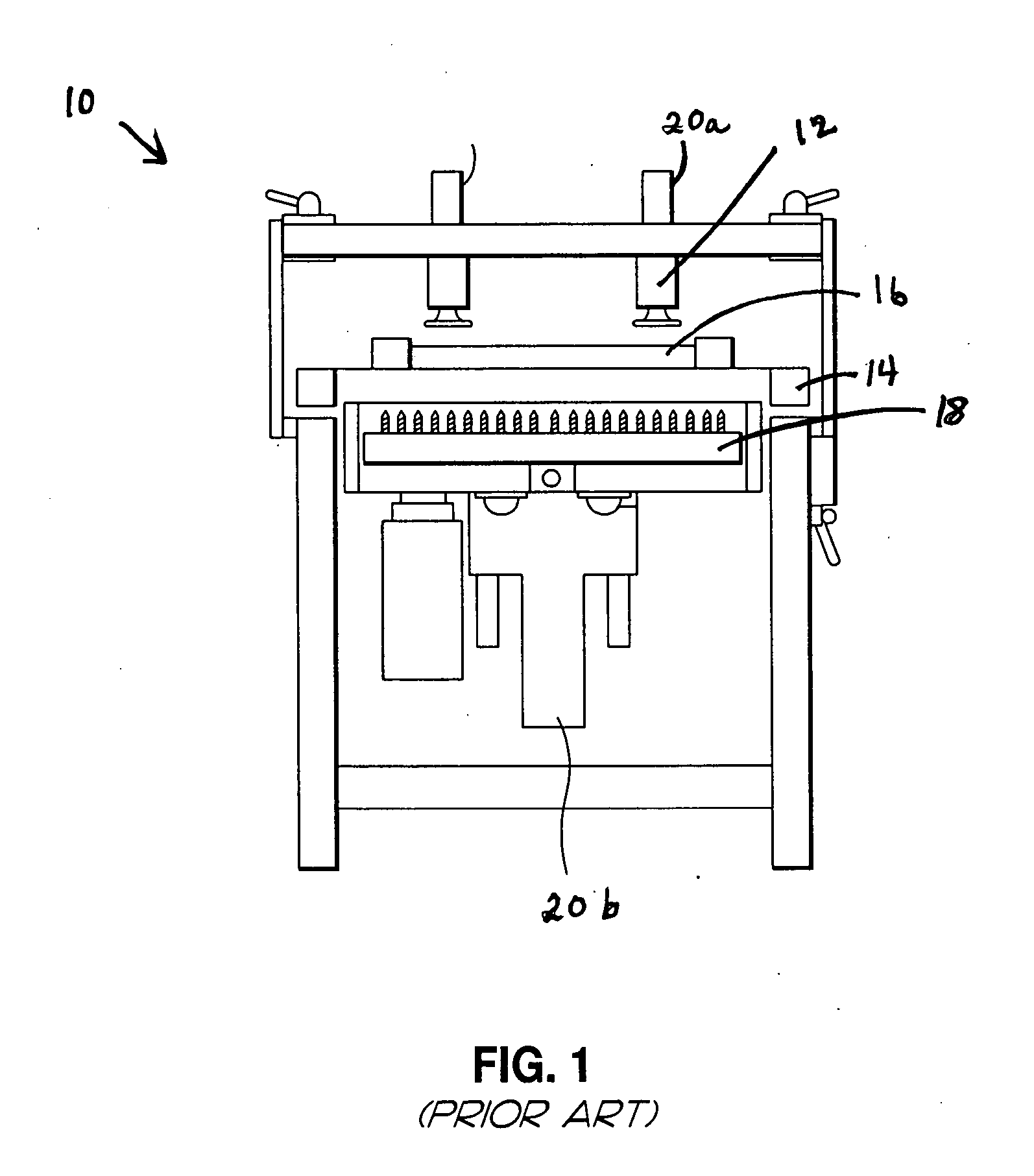
[0021]FIGS. 1-4 are for the purposes of illustrating the preferred embodiments of the present invention and not for the purposes of limiting the same. FIG. 1 illustrates a prior art line boring machine 10. In particular, the prior art line boring machine 10 comprises a push down clamp 12, bed 14, work piece 16 and drill 18. The push down clamp 12 is powered through a motor 20a located above the bed 14. The drills 18 located below the bed 14 of the up-drill 10 are vertically traversed through a motor 20b located below the bed 14. In this regard, the pressure applied to the work piece 16 by the push down clamp 12 is independent of the force applied to the work piece 16 by the drills 18 from below the bed 14. As such, the downward clamp force exerted on the work piece 16 by the clamp 12 must be manually adjusted as a function of the work to be done on the work piece 16 from the underside of the work piece 16. For example, the upward drill force exerted on the work piece 16 from the dri...


PUM

PropertyMeasurementUnit
forceaaaaaaaaaa
weightaaaaaaaaaa
pressureaaaaaaaaaa

Abstract

An up modifier is provided which includes a bed, a modifier, a clamp, a modifier linkage system, a clamp linkage system, and a lever. The modifier is disposed below the bed and is vertically traversable thereunder. The clamp is disposed above the bed and is vertically traversable thereabove. The lever defines a modifier pivot, clamp pivot and a pedal portion. The clamp pivot is interposed between the modifier pivot and the pedal portion. The clamp pivot is vertically traversable, and the modifier pivot and the pedal portion are pivotable about the clamp pivot. The modifier linkage system is attached to the modifier and the lever at the modifier pivot, and the clamp linkage system is attached to the clamp and the lever at the clamp pivot.

Description

CROSS-REFERENCE TO RELATED APPLICATIONS [0001] Not Applicable STATEMENT RE: FEDERALLY SPONSORED RESEARCH / DEVELOPMENT [0002] Not Applicable BACKGROUND OF THE INVENTION [0003] This invention relates generally to line boring machines which bore holes in a work piece from a side of the work piece resting on a bed, and more particularly, to machines which have a lever mechanically attached to both a clamp and a drill so as to advantageously produce a self-adjusting downward clamp force on the work piece which is always greater than an upward drill force. [0004] In manufacturing, a block of metal or a piece of wood is formed into a useful shape. For example, in a wood cabinet with adjustable shelves, the same may have side panels with a series of bored holes. The holes are used to insert pins such that the shelf may rest thereon to make a shelf height adjustable. To this end, the bored holes are commonly drilled out. When the holes are drilled from above, wood chips tends to clog up the h...

Claims


Application Information

Patent Timeline
Patent Type & Authority Applications(United States)
IPC IPC(8): B23B39/00B23B39/16B23Q3/06B27C3/04
CPCB23B39/003B23B39/161B23Q3/069B27C3/04Y10T408/3806Y10T408/3839Y10T408/385Y10T408/675Y10T408/6786Y10T408/6757Y10T408/563
Inventor TUCKER, BRADLEY J.
Owner TUCKER BRADLEY J
Why Eureka
Try Eureka