

Cable end connector assembly having pull tab
- Summary
- Abstract
- Description
- Claims
- Application Information
AI Technical Summary
Benefits of technology
Problems solved by technology
Method used
Image

Examples
Embodiment Construction
[0021] Reference will now be made in detail to the preferred embodiment of the present invention.
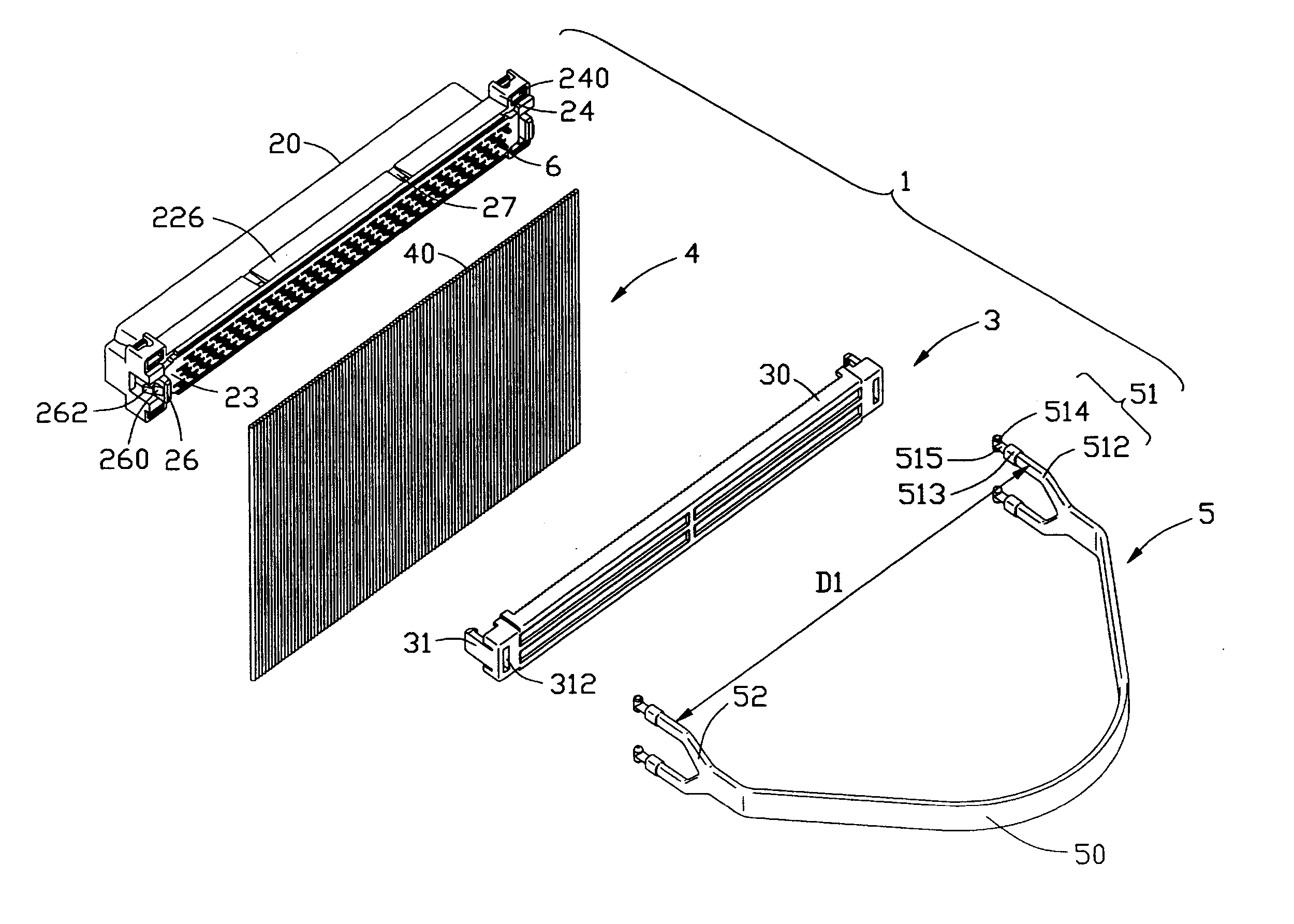
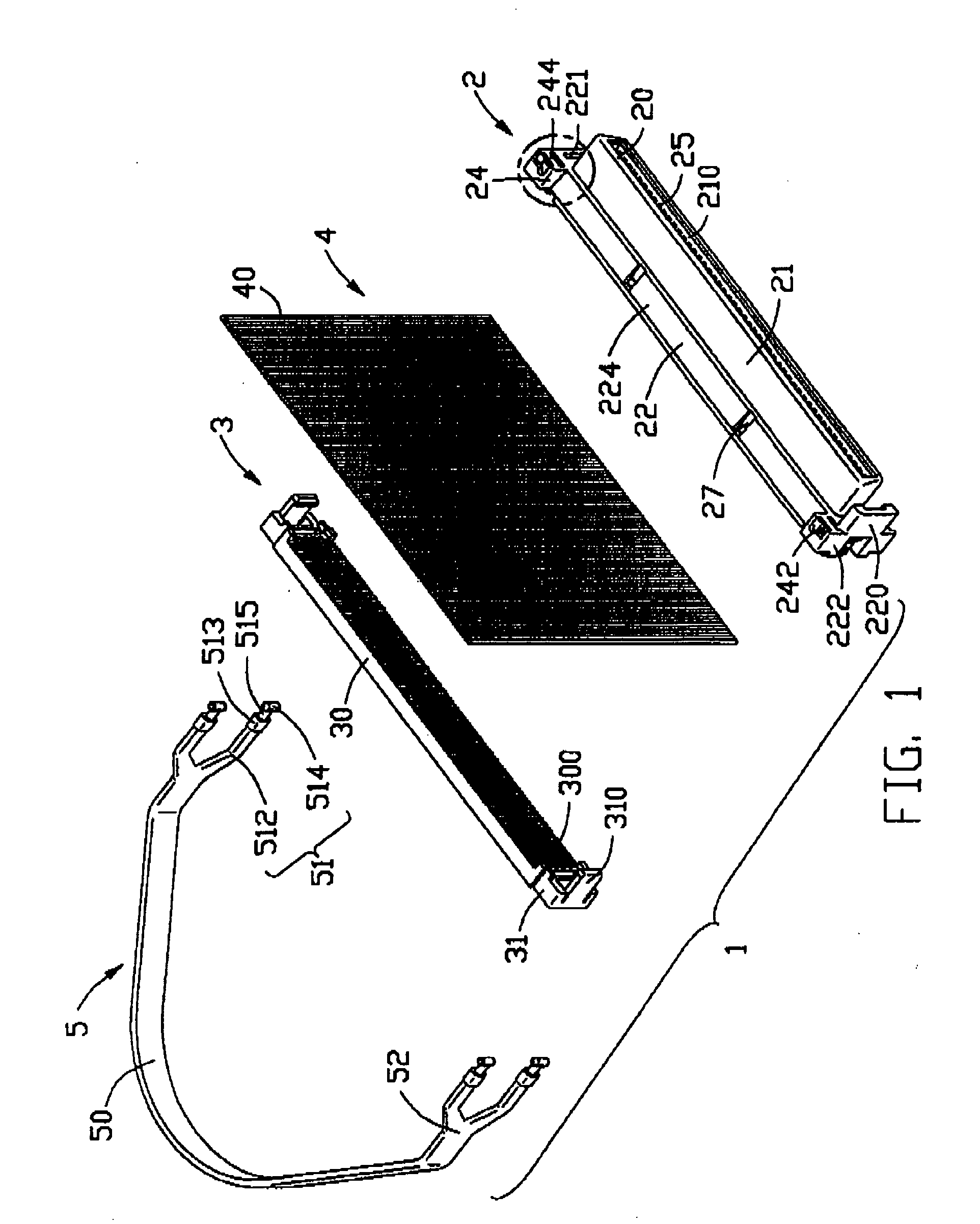
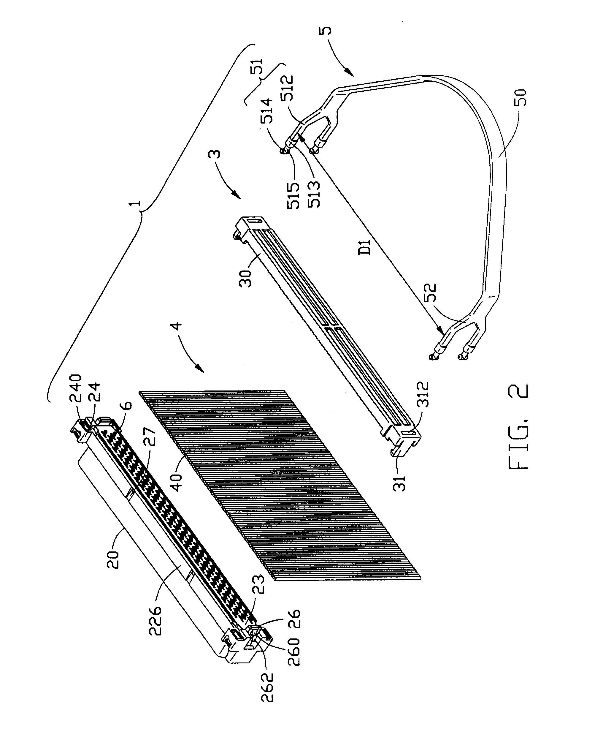
[0022] Referring to FIG. 1 and FIG. 2, a cable end connector assembly 1 in accordance with the present invention comprises an elongated insulative housing 2, a plurality of electrical contacts 6 received in the insulative housing 2, an insulated cover 3 securely attached to the insulative housing 2, a cable 4 and a pull tab 5.
[0023] Continuing to FIG. 1 and FIG. 2, the insulative housing 2 comprises a base 22 and a D-shaped mating portion 21 protruding from a center of the base 22. The insulative housing 2 also comprises a mating face 20 and a termination face 23 opposite to the mating face 20. A pair of slits 221 is respectively defined in opposite lateral ends 222 of the base 22, and a transverse U-shaped guiding post 220 extends forwardly from one lateral end 222. A pair of engaging portions 26 extends outwardly from the pair of opposite lateral ends 222 of the base 22, respectively...
PUM
 Abstract
Description
Claims
Application Information