Terminal for processing facilities

a terminal and processing facility technology, applied in the direction of electric digital data processing, program control, instruments, etc., can solve the problems of laborious and common problems, and achieve the effect of smooth processing station and enhanced information displayed in the viewing window

a terminal and processing facility technology, applied in the direction of electric digital data processing, program control, instruments, etc., can solve the problems of laborious and common problems, and achieve the effect of smooth processing station and enhanced information displayed in the viewing window

US10534346B2Active Publication Date: 2020-01-14SIG TECH AG

Image

  • Terminal for processing facilities
  • Terminal for processing facilities
  • Terminal for processing facilities

Examples


Embodiment Construction

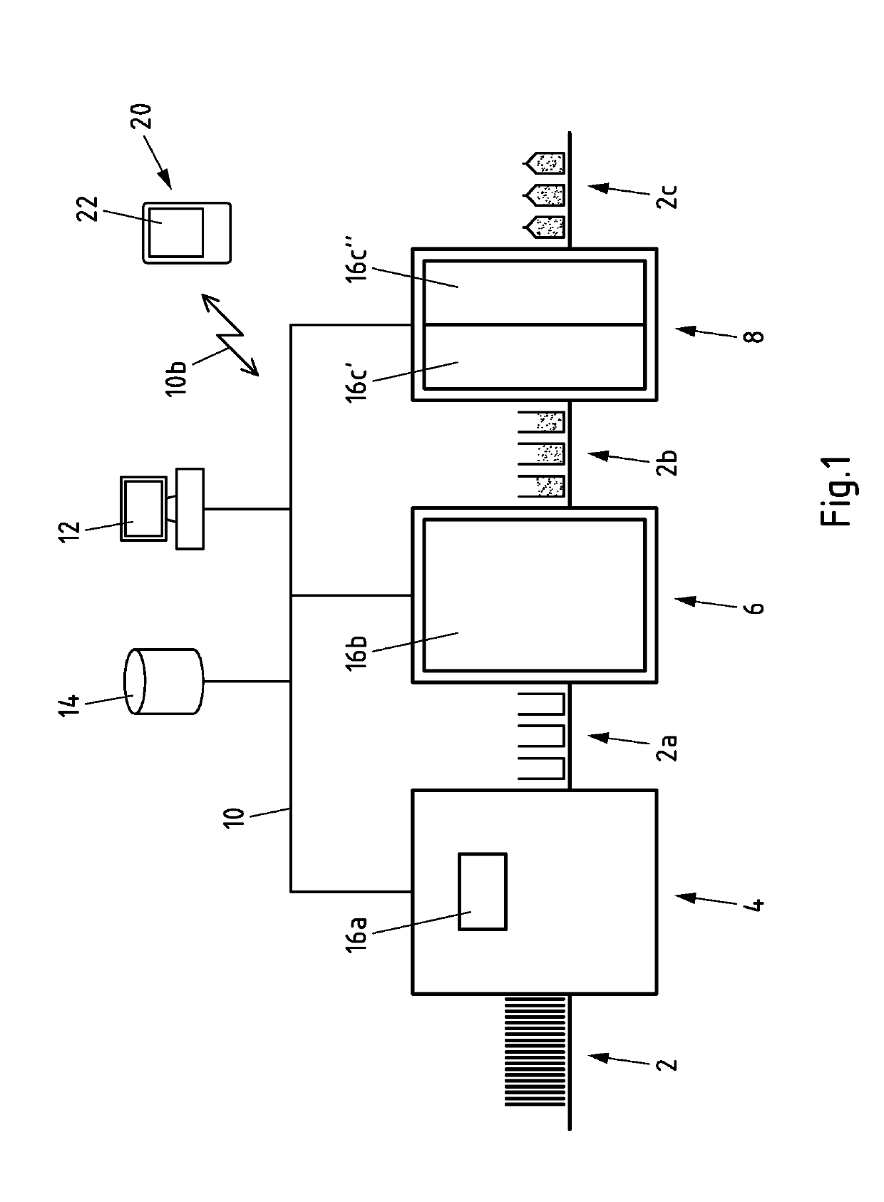
[0053]The representation of information about the state of a processing facility according to the subject matter can be demonstrated, by way of example, at a filling facility. In a filling station, for example for foodstuffs, package sleeves 2 produced from packaging material are firstly fed into an unfolding device 4. In the unfolding device 4, the package sleeves 2 initially folded flat together are unfolded and closed on one side.

[0054]The unfolded package sleeves 2a are then conveyed to a filling device 6. The foodstuff is filled into the unfolded package sleeves 2a in the filling device 6.

[0055]The package sleeves 2b filled by the filling device 6 are then conveyed to a closing unit 8. In the closing unit 8, the gables of the filled package sleeves 2b are closed, for example by welding / sealing the gable edge. The closed, filled packages 2c are then fed out of the closing unit 8.

[0056]Of course, the above representation of a filling facility is purely schematic. Notably, no ster...


PUM


Abstract

Terminal 20 for processing facilities having a communication device 28 arranged to exchange information about the processing facility with a communication partner, a screen 22 arranged to display the information about the processing facility, a position sensor 26 arranged to collect alignment information relating to an alignment of the terminal 20 and a processor 24 arranged to control the communication device 28, the screen 22 and the position sensor 26. The functionality of the terminal is extended by the fact that the processor sets a function of the terminal 20 dependent on alignment information from the position sensor 26.

Description

CROSS REFERENCE TO RELATED APPLICATIONS[0001]This application is the United States national phase of International Application No. PCT / EP2015 / 064949 filed Jul. 1, 2015, and claims priority to German Patent Application No. 10 2014 012 185.2 filed Aug. 20, 2014, the disclosures of which are hereby incorporated in their entirety by reference.BACKGROUND OF THE INVENTIONField of the Invention[0002]The subject matter relates to a terminal for processing facilities and to a system having a terminal and a processing facility, as well as to the use of a terminal for a processing facility.Description of Related Art[0003]Present-day processing facilities (also known as units) in the manufacturing industry, for example production facilities, production lines, packaging facilities, filling facilities or the like, are getting more complex. The requirements, regarding hygiene for example, are getting stricter and stricter due to statutory provisions. The dimensional accuracy and process reliabilit...

Claims


Application Information

Patent Timeline
14 Jan 2020
Publication
US10534346B2
IPC
G05B15/00; B65B17/00; G06F3/0484; G06F1/16; G05B19/409; G06F3/0346; B65B57/00
CPC
B65B17/00; G05B19/409; G06F1/1694; G06F3/04847; G06F3/0346; G05B2219/32014; B65B57/00; G05B2219/39449
Inventors
HOLZKÄMPER, PETER; HOFMANN, THOMAS