
Serviceable vortex-type filter assembly and method for servicing same

a technology of vortex-type fluid filter and assembly, which is applied in the direction of vortex flow apparatus, separation process, dispersed particle separation, etc., can solve the problems of assembly replacement, high prone to plant material plugging in both passages and filtration chambers, and cannot be cleaned manually. , to achieve the effect of quick inspection and removal

Active Publication Date: 2005-01-27
DEERE & CO
View PDF3 Cites 29 Cited by
  • Summary
  • Abstract
  • Description
  • Claims
  • Application Information

AI Technical Summary

Benefits of technology

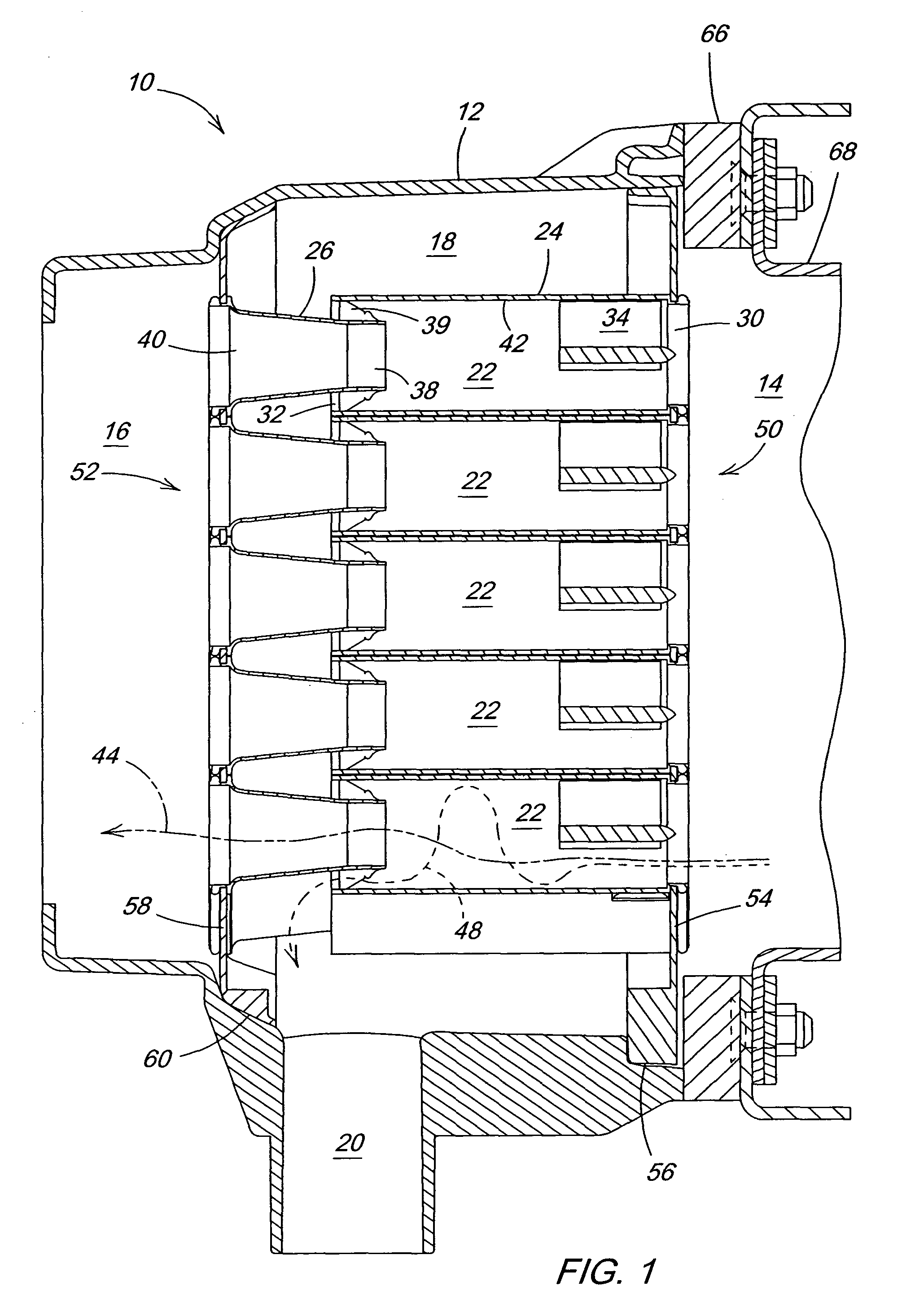
[0009] In a first illustrated embodiment, the modules are secured within the housing by a flange that mates inlet plumbing to the filter assembly. When the flange is removed, the modules are removable at the inlet portion of the filter housing. In a second illustrated embodiment, the modules are secured within the housing via an access panel, through which the modules are also removed for servicing. When closed, the access panel secures the inlet module and outlet module within the housing. With either arrangement, an operator can quickly inspect and remove one or both modules for servicing. Additionally, servicing can be completed while remaining in the operating environment without the use of special tools.

Problems solved by technology

As such, the typical vortex-type filter assembly is a sealed unit and does not allow for manual cleaning.
Thus, when the scavenge method becomes ineffective and the filtration chamber becomes plugged with separated material, or when the passages themselves become plugged with material, the filter assembly must be replaced.
However, under certain operating conditions with an agricultural harvester, particularly when harvesting safflower, both the passages and filtration chamber are highly prone to plugging with plant material.
Additionally, under certain operating conditions where the air and / or debris are high in moisture, the filtration chamber is highly prone to become caked with moist separated material, which can harden into a brick under heating by the engine.
The high cost and amount of downtime attributed to frequent replacement of the filter assembly is very undesirable.

Method used


Image

  • Serviceable vortex-type filter assembly and method for servicing same
  • Serviceable vortex-type filter assembly and method for servicing same
  • Serviceable vortex-type filter assembly and method for servicing same

Examples


Embodiment Construction

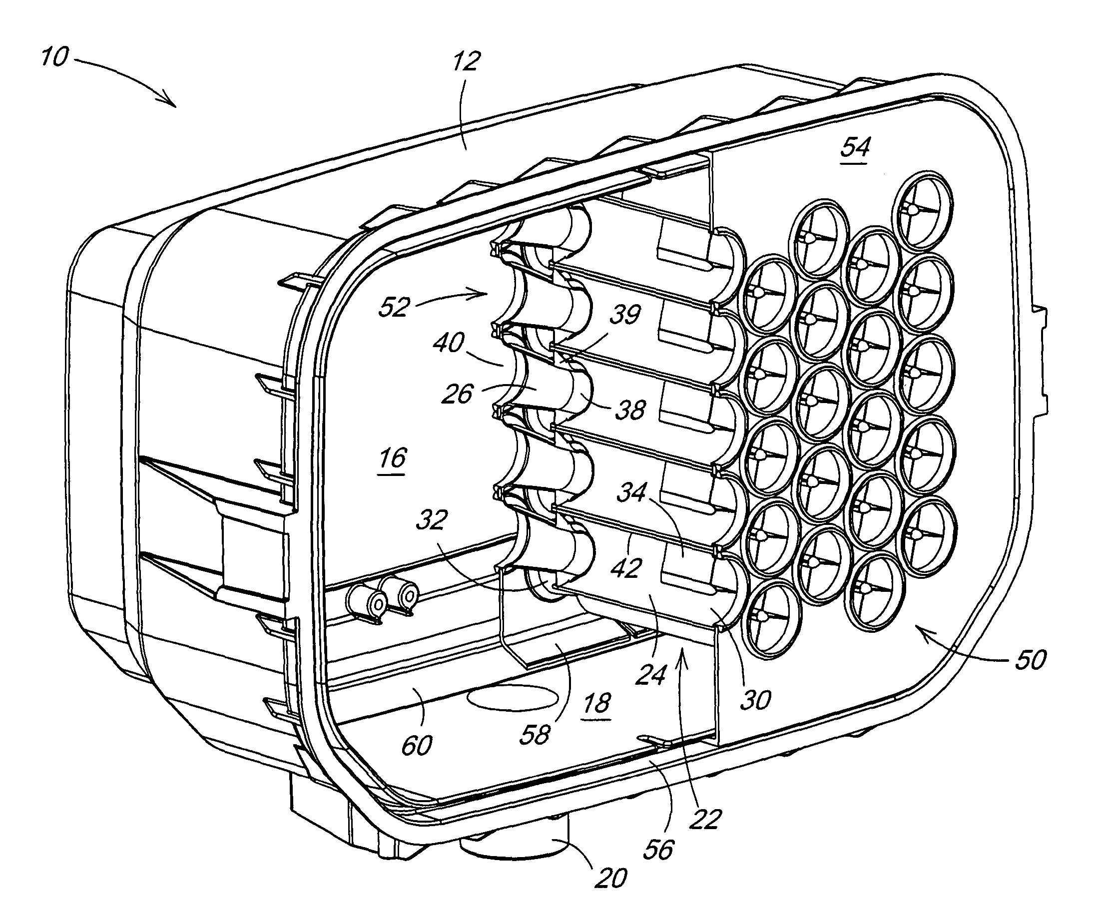
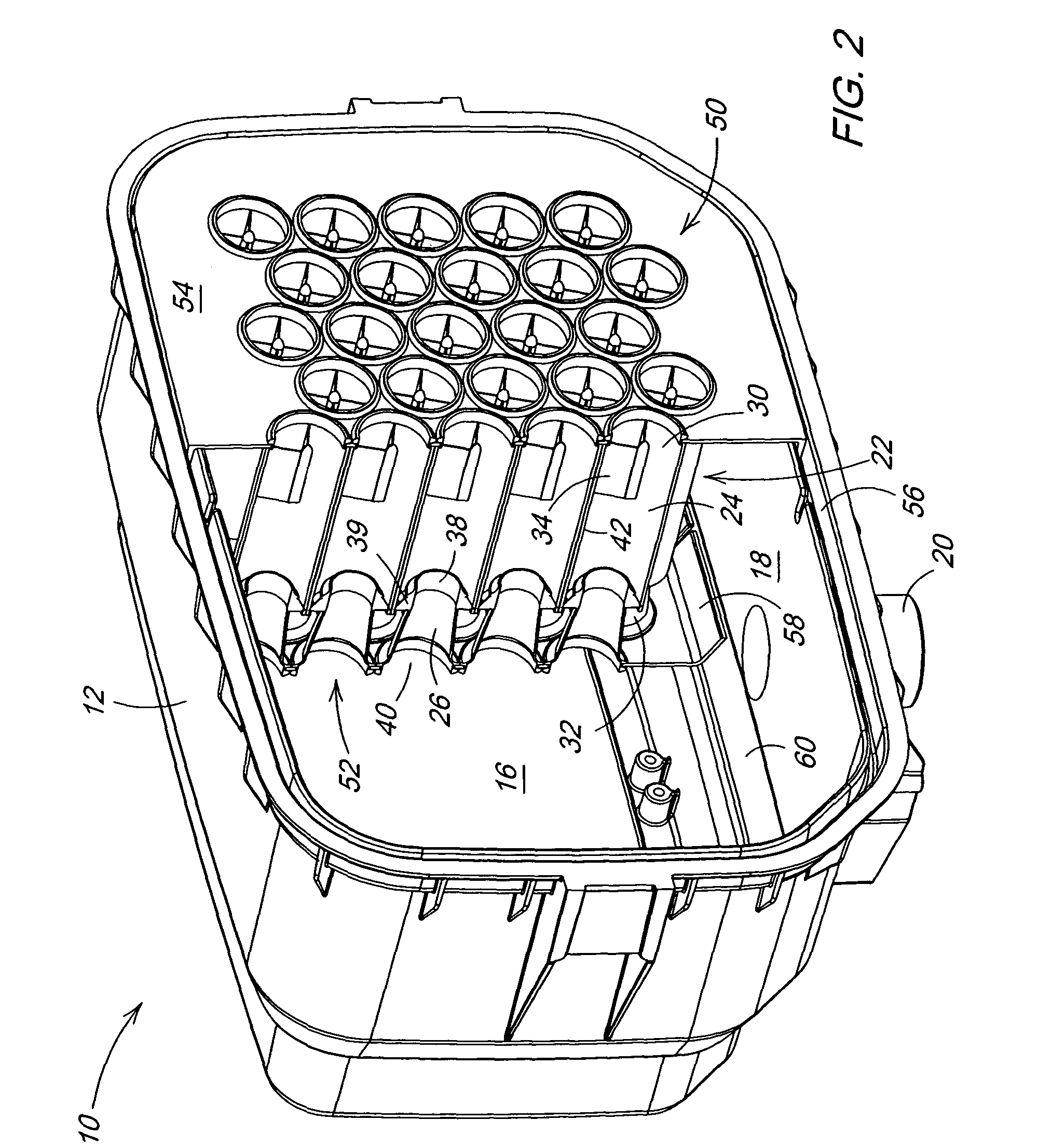
[0015]FIG. 1 shows a first illustrated embodiment of the present invention, a vortex-type filter assembly 10 with removable working modules 50 and 52. The filter assembly 10 comprises a rectangular housing 12 having an inlet portion 14, an outlet portion 16, and a filtration chamber 18. Extending from the housing 12, proximate the filtration chamber 18, is a scavenge port 20. Unfiltered fluid enters the filter assembly 10 at the inlet portion 14. Filtered fluid is delivered from the filter assembly 10 at the outlet portion 16, while fluid containing separated material is drawn from the filter assembly 10 at the scavenge port 20. The component parts of the filter assembly 10 may be formed from a variety of suitable materials, including steel, aluminum, or engineered plastics. Although illustrated as a rectangular filter assembly, a cylindrical shape could also be used.

[0016] Arranged within the housing 12 are several vortex-type filters 22 that extend axially within the filtration c...


PUM

PropertyMeasurementUnit
centrifugal forceaaaaaaaaaa
cylindrical shapeaaaaaaaaaa
shapeaaaaaaaaaa

Abstract

A vortex-type filter assembly comprising a housing, a removable inlet module, and a removable outlet module. The housing comprises an inlet portion, a filtration chamber, and an outlet portion. The inlet module separates the inlet portion from the filtration chamber, and has one or more vortex generating inlet passages. The outlet module separates the filtration chamber from the outlet portion, and has one or more outlet passages. There is one outlet passage cooperating with every one inlet passage for filtering debris from the fluid. One or both of inlet module and the outlet module may be removed to facilitate servicing of the filter assembly.

Description

FIELD OF THE INVENTION [0001] The present invention relates to vortex-type fluid filters, and more specifically, a filter assembly with removable working modules. BACKGROUND OF THE INVENTION [0002] Vortex-type filters are well known and used extensively for filtering fluids, including both liquids and gases. These filters are advantageous because they provide high separation efficiency with minimal pumping losses. Vortex-type filters can be used in a variety of applications, such as separating debris from fluids, separating heavier fluids from lighter fluids, separating particulates from gases, or separating liquid fluids from gas fluids. [0003] A vortex-type filter essentially comprises a vortex generating inlet passage, and a cooperating outlet passage. Both passages may be cylindrical or somewhat conical, and are axially aligned to one another. The entrance of the outlet passage is smaller than the exit of the inlet passage, and is located proximate to the exit of the inlet passa...

Claims


Application Information

Patent Timeline
Patent Type & Authority Applications(United States)
IPC IPC(8): B01D45/16B01D50/00B04C3/04
CPCB01D45/16B04C3/04B01D50/002B01D50/20
Inventor SHEIDLER, ALAN DAVIDLOVETT, BENJAMIN MAXPARK, YONG HO
Owner DEERE & CO
Learn More