Method and apparatus for low cost, current and voltage sense circuits with voltage drop

Inactive Publication Date: 2005-01-27
POWER INTEGRATIONS INC
View PDF14 Cites 15 Cited by
  • Summary
  • Abstract
  • Description
  • Claims
  • Application Information

AI Technical Summary

Benefits of technology

[0010] In yet another aspect of the invention, a voltage drop compensation circuit is described including a voltage sense circuit coupled across a voltage output. The voltage sense circuit includes a voltage reference coupled to drive the base of the bipolar transistor when the voltage at the voltage output exceeds a sense voltage of the voltage sense circuit. A compensation resistor is coupled to the voltage output to carry a current that substantially represents the current that flows from the voltage output to a load that is coupled to the output. The sum of the voltage across the compensation resistor and the forward base emitter voltage of the bipolar transistor is applied across a series combination of a second resistor and a diode. The current through the second resistor is used to alter the sense voltage of the voltage sense circuit. In one embodiment, the sense voltage is increased as the current to the load increases. In one embodiment, the diode is replaced by a short circuit. In one embodiment, the voltage reference is a zener and the sense voltage of the voltage sense circuit is the sum of the voltage across the zener and the forward base emitter voltage (VBE) of the bipolar transistor and, the current through the second resistor is passed through the zener. In one embodiment, the voltage sense circuit further includes a third resistor and the sense voltage is the sum of the voltage across the voltage reference, the voltage across the third resistor and the forward emitter bias voltage of the bipolar transistor and, the current through the second resistor is passed through the third resistor. In one embodiment, the diode is a PN junction diode. In one embodiment, the bipolar transistor drives an LED of an optocoupler and the optocoupler is part of a feedback circuit of switched mode power supply.
[0011] In still another aspect of the present invention, a voltage drop compen

Problems solved by technology

Most of these chargers require relatively accurate and expensive circuitry to meet the specified current and voltage tolerances over temperature.
TL431 voltage reference is generally more expensive than a simple zener reference.
However, zeners are generally difficult to get at tolerance below 2% and the zener voltage varies with the current through it, resulting in a poorer load regulation in circuits that have zener currents that vary with output load due to low gain of the feedback loop.
In addition, they are only available in certain standard voltage values, which makes it difficult to center the output voltage at the optimum point for the best tolerance.
The constant current limit set by such a circuit, however, has a large temperature variation due to the high temperature coefficient of VBE (−2 mV / ° C.).

Method used


Image

  • Method and apparatus for low cost, current and voltage sense circuits with voltage drop
  • Method and apparatus for low cost, current and voltage sense circuits with voltage drop
  • Method and apparatus for low cost, current and voltage sense circuits with voltage drop

Examples


Embodiment Construction

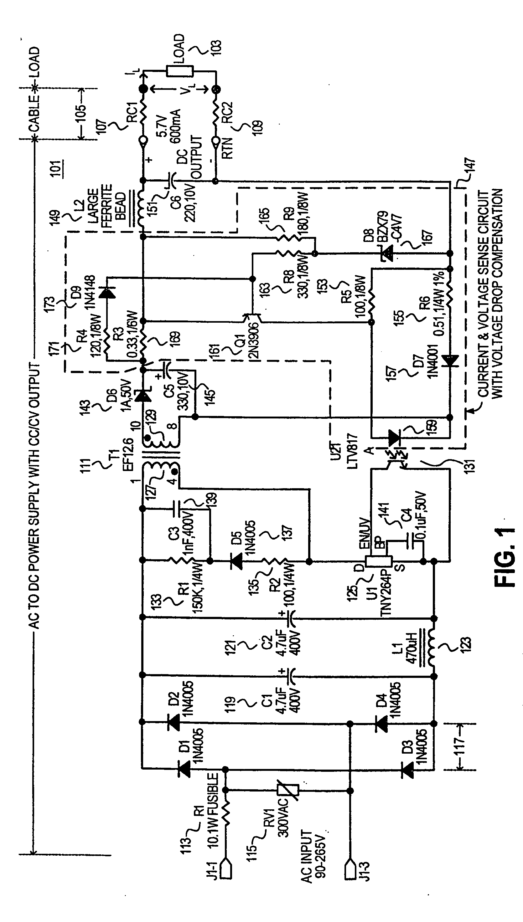
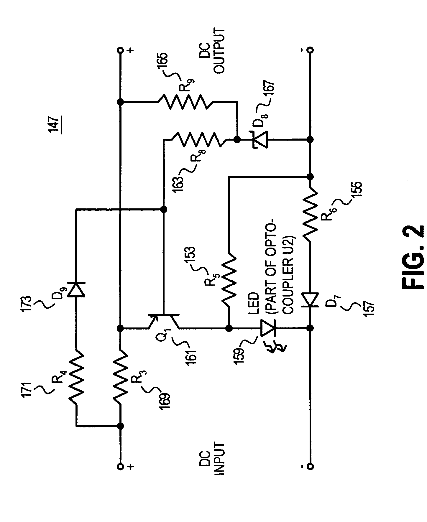
[0018] Embodiments of methods and apparatuses for providing current sensing, voltage sensing and voltage drop compensation in circuits, such as for example but not limited to power supply circuits, are disclosed. In the following description, numerous specific details are set forth in order to provide a thorough understanding of the present invention. It will be apparent, however, to one having ordinary skill in the art that the specific detail need not be employed to practice the present invention. In other instances, well-known materials or methods have not been described in detail in order to avoid obscuring the present invention.

[0019] Reference throughout this specification to “one embodiment” or “an embodiment” means that a particular feature, structure or characteristic described in connection with the embodiment is included in at least one embodiment of the present invention. Thus, the appearances of the phrases “in one embodiment” or “in an embodiment” in various places th...


PUM

PropertyMeasurementUnit
Poweraaaaaaaaaa
Currentaaaaaaaaaa
Electric potential / voltageaaaaaaaaaa

Abstract

Methods and apparatuses to sense current and voltage in circuits with voltage drop. In one aspect of the invention, a sense circuit includes a series combination of a diode and a resistor in the path of the current to be sensed, the voltage across this series combination coupled to drive a light emitting diode (LED).

Description

RELATED APPLICATION [0001] This application claims priority to U.S. provisional application Ser. No. 60 / 306,719, filed Jul. 20, 2001, entitled “Method And Apparatus For Low Cost Current And Voltage Sense Circuits With Voltage Drop.”BACKGROUND OF THE INVENTION [0002] 1. Field of the Invention [0003] The present invention relates generally to circuits with voltage and current sensing and, more specifically, the present invention relates to current and voltage sensing in circuits with voltage drop. [0004] 2. Background Information [0005] Most battery operated portable electronic products such as cell phones, personal digital assistants (PDAs), etc. require a low power alternating current (AC) to direct current (DC) charger power supply with a constant voltage and constant current (CC / CV) characteristics for charging batteries. Most of these chargers require relatively accurate and expensive circuitry to meet the specified current and voltage tolerances over temperature. [0006] In a kno...

Claims


Application Information

Patent Timeline
IPC IPC(8): G01R19/165H02M3/28H03K17/78
CPCG01R19/0084G01R19/0092G01R31/40G01R19/16571G01R19/16523H02M3/33507
Inventor BALAKRISHNAN, BALUODELL, ARTHUR B.
Owner POWER INTEGRATIONS INC
Why Eureka
Try Eureka