Crane safety devices and methods

a safety device and crane technology, applied in the field of crane safety methods and devices, can solve the problems of not widely used conventional crane safety devices that do not inform the operator, the warning beacon on the safety device often becomes obscured by the load, and the conventional crane safety devices mounted proximate to the moving crane parts are not widely used, so as to increase the safety and efficiency of the crane operating environment, eliminate the beeping emitted, and increase the safety of the worker.

a safety device and crane technology, applied in the field of crane safety methods and devices, can solve the problems of not widely used conventional crane safety devices that do not inform the operator, the warning beacon on the safety device often becomes obscured by the load, and the conventional crane safety devices mounted proximate to the moving crane parts are not widely used, so as to increase the safety and efficiency of the crane operating environment, eliminate the beeping emitted, and increase the safety of the worker.

US20050017867A1Inactive Publication Date: 2005-01-27SHAW JACK B +1

Image

  • Crane safety devices and methods
  • Crane safety devices and methods
  • Crane safety devices and methods

Examples


Embodiment Construction

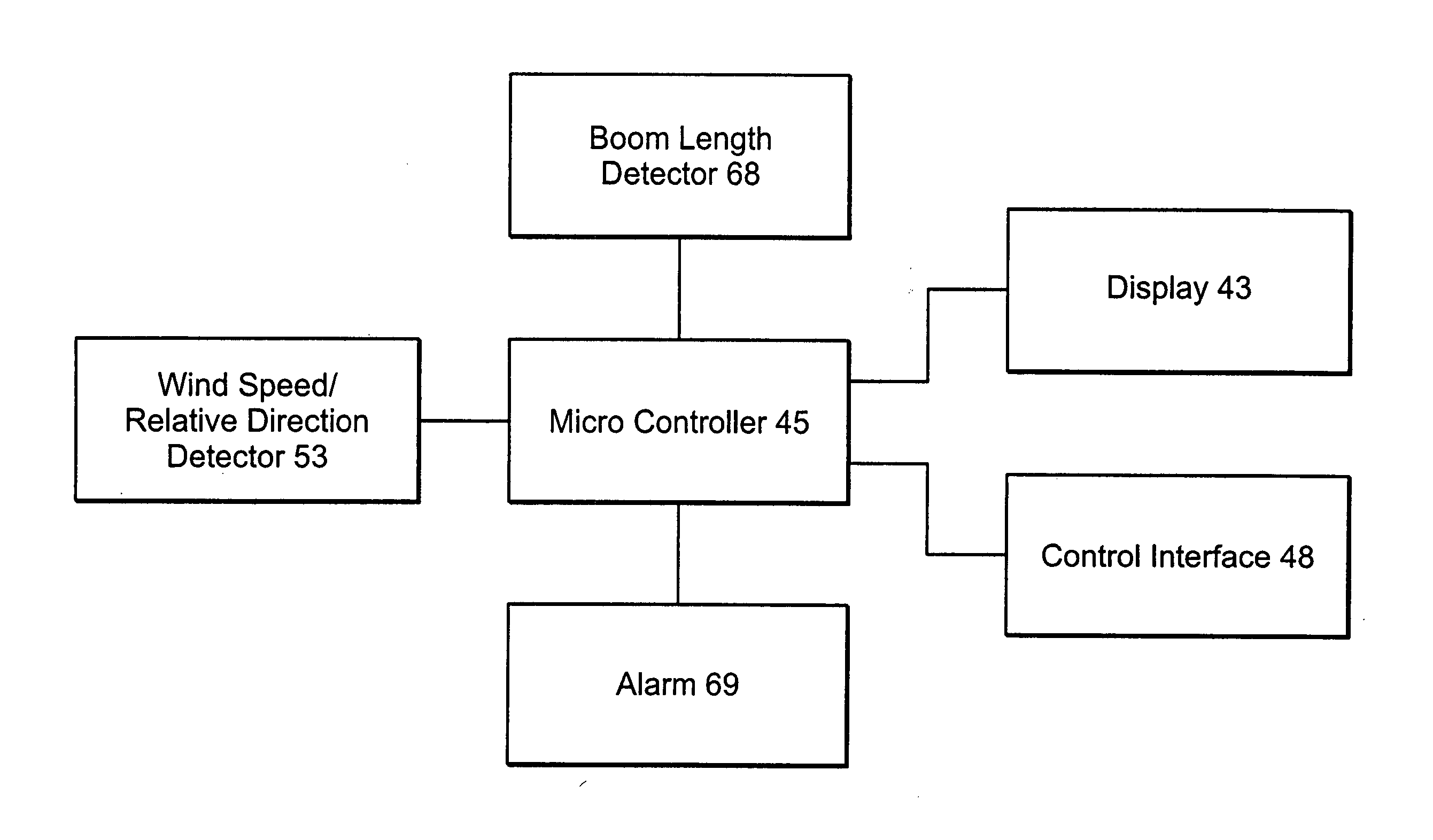
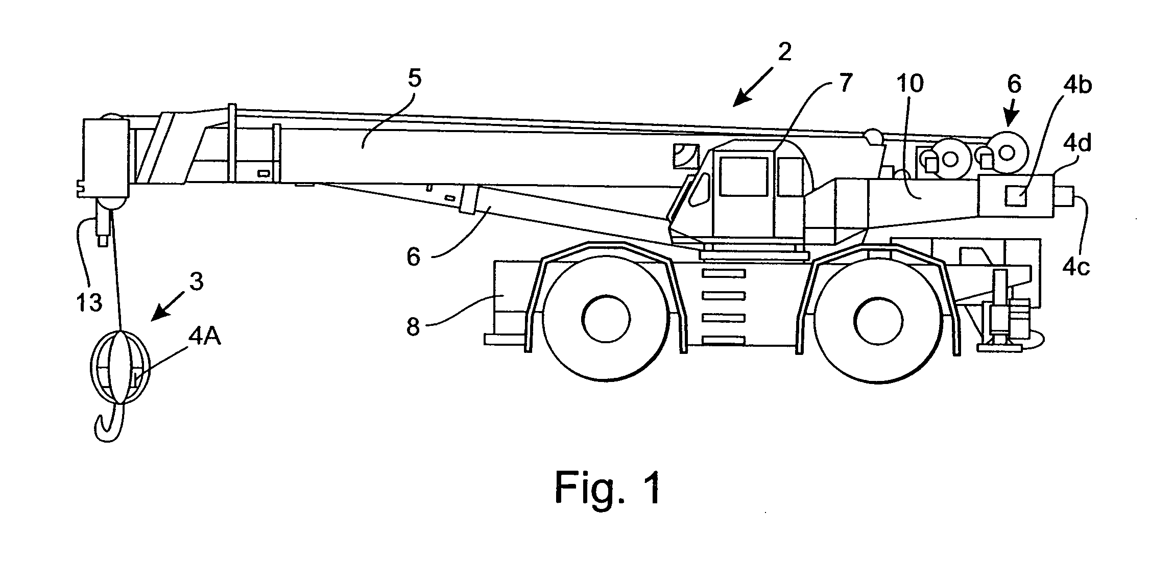
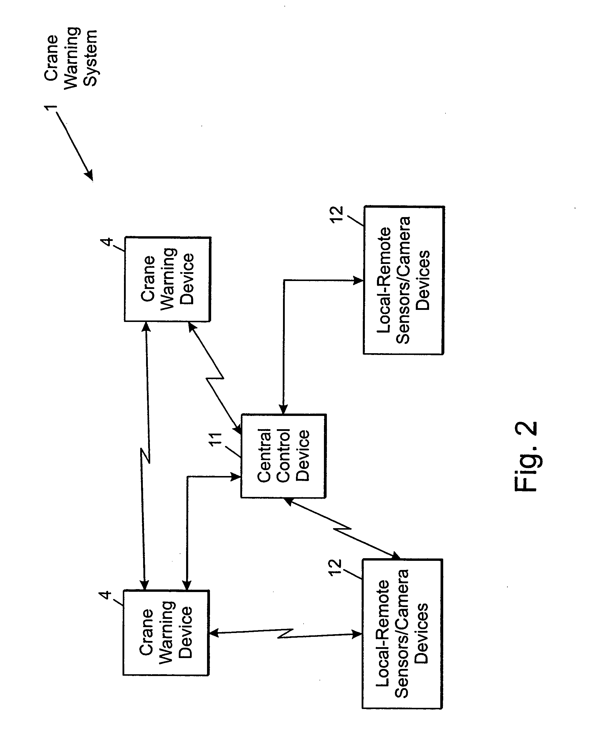
[0029] Referring to FIGS. 1 and 2, a crane warning system 1 is incorporated in a crane 2 to improve the safety of workers (not shown) in the vicinity of the crane. The crane 2 typically includes a boom 5, various movement mechanisms 6 to move the boom 5, carriage (not shown in the embodiment of FIG. 1), and / or ball 3 in any one of a plurality of directions. The movement mechanisms may include any hydraulic, electromotive, mechanical, and / or other mechanisms well known in the art to cause motion of the ball 3, boom 5, and / or carriage (not shown). For the purposes of this specification, the boom includes any jib or other extension that may be attached to the boom. The crane 2 typically includes a cab 7 for accommodating an operator (not shown). In many cases, the cab 7 is either partially or completely enclosed to provide a controlled environment for the operator. The crane 2 may include one or more crane warning devices 4 strategically disposed about the crane 2. In the embodiment sh...


PUM


Abstract

An improved crane warning system which includes acceleration sensors, motion sensors, hydraulic sensors, remote communications and / or a camera. The crane warning system may include a crane warning device integrated into the ball of the crane.

Description

RELATED APPLICATIONS [0001] This application is a continuation-in-part of U.S. patent application Ser. No. 09 / 030,249, filed on Feb. 25, 1998, which in turn is a continuation-in-part application of U.S. Provisional Patent Application No. 60 / 039,825, filed on Feb. 27, 1997, both of which applications are expressly incorporated entirely herein by reference.TECHNICAL FIELD [0002] The present invention relates to crane safety methods and devices and, in particular, to improved safety devices and methods which warn workers of the movement of portions of a crane. The invention also relates to a system for safely controlling the operation of crane in response to prevailing wind conditions. BACKGROUND OF THE INVENTION [0003] Conventional crane safety devices (e.g., U.S. Pat. No. 5,019,798) are subject to a number of deficiencies. For example, the devices must be manually attached to the load each time that a new load is secured to the crane. Further, a warning beacon on the safety device of...

Claims


Application Information

Patent Timeline
27 Jan 2005
Publication
US20050017867A1
IPC
B66C13/44; B66C13/46; B66C15/04; B66C15/06
CPC
B66C13/44; B66C15/06; B66C15/04; B66C13/46
Inventors
SHAW, JACK B.; SHAW, JOHN B. JR.