
Illuminator, projection display device and method for driving the same

Active Publication Date: 2005-01-27
SEIKO EPSON CORP
View PDF7 Cites 58 Cited by
  • Summary
  • Abstract
  • Description
  • Claims
  • Application Information

AI Technical Summary

Benefits of technology

[0015] The light control based on the usage information allows flexible light control in touch with reality. For example, when the usage information relates to the brightness of viewing environment, the dimming amount of the light source can be reduced when the ambient is bright, while the dimming amount is increased when the ambient is dark. Thus, the problem of insufficient brightness caused by excessive light control can be solved.
[0017] With this arrangement, the dynamic range of the projection image can be expanded by appropriate adjustment of the light flux of illumination depending on the image information. Also the problem of insufficient brightness and the like can be solved without quality loss in image expression by limiting the dimming range of the light flux within a fixed range depending on the kind of the image and viewing environment. For example, when the viewing environment is bright or the image itself is bright and so light control works negatively, the dimming range is made narrower than normal (that is, the maximum allowable dimming amount is reduced), so that the problem of the insufficient brightness can be solved.
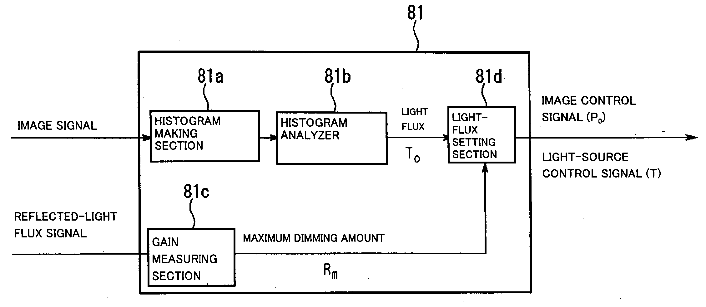
[0020] The example of automatically measuring the usage information can include the structure in which the device has brightness measuring device for measuring the brightness of the projection-image viewing environment (for example, the brightness around the device and the brightness around the screen) and in which the dimming-range setting device sets the range on the basis of the brightness of the viewing environment. With this arrangement, for example, reducing the dimming range as the viewing environment becomes brighter (that is, the maximum allowable dimming amount is reduced) allows the entire image to be displayed more brightly than usual when the ambient is bright. Accordingly, high-quality projection images can be enjoyed without the feeling of insufficient brightness even in a bright room.
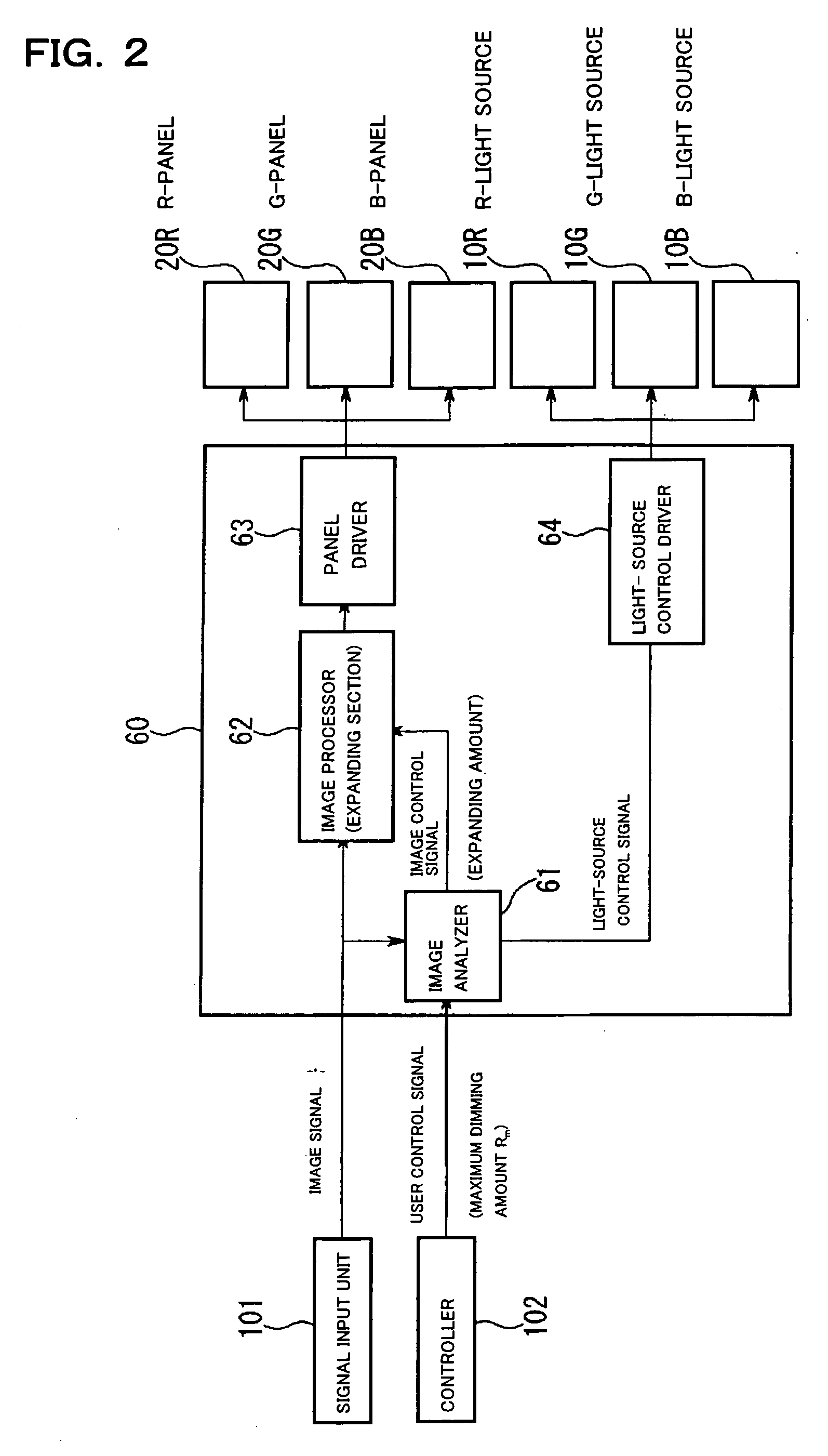
[0023] Preferably, the projection display device further can include an image-signal expanding device for expanding the image signal on the basis of the dimming amount of the light source as the driving device. With the arrangement, first, an dimming range in which dimming is allowed is set by the dimming-range setting device on the basis of use information. The light flux of the light source is adjusted within the dimming range on the basis of the image signals per unit time (during a period), the image signals are expanded on the basis of the dimming amount of the light source, and the expanded image signals are sent to the light modulation means; thus, an image is formed. Accordingly, the dynamic range of the projection display device can be expanded to realize a projection display device with high image expression and adaptability to usage environment.
[0025] With the conventional light control in which the dimming amount is not limited, the light flux of the light source is always adjusted with a set dimming amount. Therefore, the product of the expansion amount and the light flux needs to be set to one or less to make the expanded image signal equal to or less than the maximum displayable gray level. On the other hand, with the light control in which the dimming is limited to be lower than a certain value, as in the invention, the signal that has the maximum gray level of the image signals is not expanded to the maximum displayable gray level even by the conventional expanding process based on the limited dimming amount (the process in which the product of the expansion amount and the light flux becomes one or less). In other words, when the set dimming amount comes out of the dimming range, there is some margin of gray levels in a high gray-level region even if expanding process is performed under the condition that the product of the expansion amount and the light flux is one, so that sufficient tone reproduction is not obtained. Accordingly, setting the product of the expansion amount and the light flux higher than one with the dimming limited, as in this arrangement, a decrease in tone reproduction can be prevented.

Problems solved by technology

Thus the light flux of illumination is excessively adjusted in some cases to apply a stress to viewers.

Method used


Image

  • Illuminator, projection display device and method for driving the same
  • Illuminator, projection display device and method for driving the same
  • Illuminator, projection display device and method for driving the same

Examples


Embodiment Construction

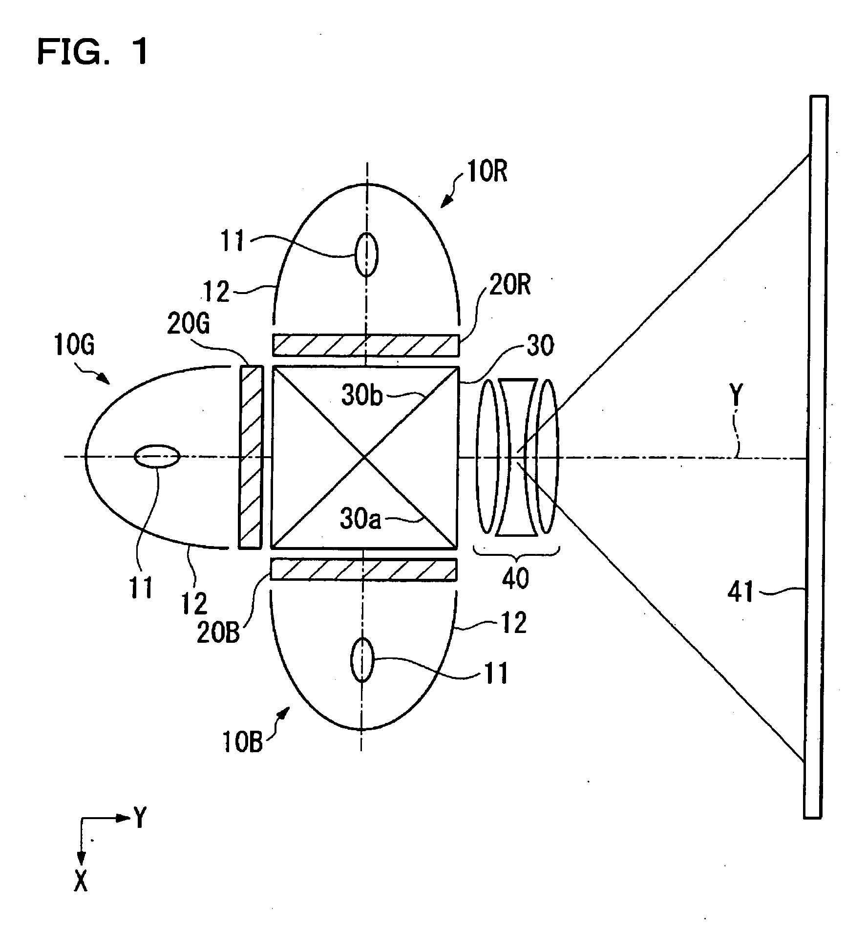
[0041] Referring to FIGS. 1 to 8, a projection display device according to a first embodiment of the invention will now be described.

[0042] The projection display device of the embodiment is a three-light-valve-liquid-crystal projection display device including a transmissive liquid-crystal light valve for each of different colors of red (R), green (G), and blue (B).

[0043]FIG. 1 shows the schematic arrangement of the projection display device, wherein reference numerals 10R, 10G, and 10B denote three light sources constructing an illuminator of the invention, respectively, reference numerals 20R, 20G, and 20B denote liquid-crystal light valves (light modulation device), numeral 30 denotes a cross-dichroic prism, numeral 40 denotes a projector lens (projection device), and numeral 41 denotes a screen.

[0044] The light sources 10R, 10G, and 10B are color light sources capable of emitting red light, green light, and blue light, respectively, wherein the respective light sources 10 (1...


PUM


Abstract

The invention provides a projection display device capable of appropriate light control depending on the kind of the image, the ambient brightness and so on, a method for driving the same, and an illuminator used in the same. The light flux of illumination can be adjusted on the basis of image information. The allowable light control range (dimming control) can be optimally set depending on the information (usage information) on the kind of viewed content, the brightness of viewing environment, the gain of a screen and the like.

Description

BACKGROUND OF THE INVENTION [0001] 1. Field of Invention [0002] The present invention relates to an illuminator, a projection display device having the same, and a method for driving the same. More particularly, the invention relates to a projection display device having excellent image expression and an illuminator used therein. [0003] 2. Related Art [0004] Information technology devices have greatly been developed, thus increasing a demand for display devices with high resolution, low power consumption, and low profile, and thus advancing research and development. Among them, liquid crystal displays are expected to be able to change optical characteristics by electrically controlling the alignment of liquid crystal molecules to thereby match the above-described needs. A known example of such liquid crystal displays is a projection display device (liquid crystal projector) that projects an image emitted from an optical system using a liquid-crystal light valve, on an enlarged scale...

Claims


Application Information

Patent Timeline
IPC IPC(8): G02B27/28G02F1/133G02F1/13G02F1/13357G03B21/00G03B21/14G03B21/20G09G3/20G09G3/34G09G3/36H04N5/74H04N9/31H04N17/00
CPCG09G3/3406G09G2320/0271G09G2320/0285G09G2320/0606G09G2320/062H04N9/3155G09G2360/144G09G2360/145G09G2360/16H04N5/74G09G2320/0646G03B21/20G02B27/28
Inventor YOSHIDA, SHOHEI
Owner SEIKO EPSON CORP
Learn More